
A kind of gradient material metal mold 3D printing integrated preparation method

A metal mold and 3D printing technology, which is applied in the direction of additive manufacturing, additive processing, and improvement of process efficiency, can solve problems such as difficulty in achieving continuous and uniform changes in material components, waste of precious element usage, and complex process equipment, etc., to achieve The effect of shortening the preparation cycle, reducing the preparation cost and simple operation process

Active Publication Date: 2018-03-13
四川三阳激光增材制造技术有限公司
View PDF11 Cites 0 Cited by
  • Summary
  • Abstract
  • Description
  • Claims
  • Application Information

AI Technical Summary

Problems solved by technology

Common gradient material preparation methods include powder molding preparation method, physical vapor deposition preparation method, chemical vapor deposition preparation method, plasma spraying preparation method, electroplating method, etc.; however, although these preparation methods have their own advantages, they also have some limitations. For example, it is difficult to achieve continuous and uniform change of material components in the powder molding preparation method, and it is difficult to obtain thick materials by the vapor deposition preparation method, etc.
The process equipment of these preparation methods is also relatively complicated, and the preparation process is relatively cumbersome. In addition, there are disadvantages such as waste of precious element usage, low precision, and relatively poor mechanical properties in the manufacturing process.

Method used


Image

  • A kind of gradient material metal mold 3D printing integrated preparation method

Examples


Embodiment Construction

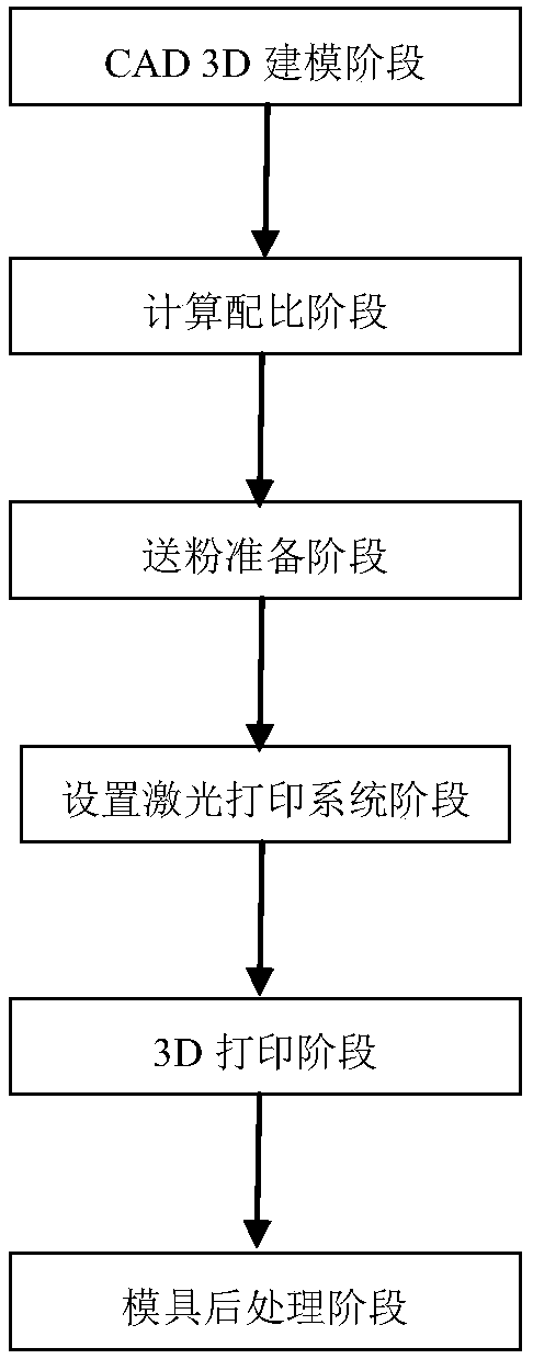
[0023] Attached below figure 1 An integrated preparation method for 3D printing of a gradient material metal mold according to the present invention will be described in detail.

[0024] An integrated preparation method for gradient material metal mold 3D printing, the preparation method comprising the following steps:

[0025] 1) CAD 3D modeling stage: The industrial computer on the workbench has built-in CAD 3D modeling software and establishes a 3D model diagram, and performs layered slice processing on the established mold 3D model diagram to obtain the material component information and slice of each slice The surrounding contour trajectory of the slice, wherein the thickness of the layered slice is 10-100 μm; according to the material component information of each slice and the surrounding contour trace information of the slice, the scanning path of the laser printing system and the powder feeder is generated;

[0026] 2) Calculation ratio stage: The industrial computer...


PUM

PropertyMeasurementUnit
diameteraaaaaaaaaa
particle diameteraaaaaaaaaa

Abstract

The invention relates to an integrated preparation method for gradient material metal mold 3D printing. The preparation method comprises the following steps: 1) CAD 3D modeling stage; 2) calculation ratio stage; 3) powder feeding preparation stage; 4) setting laser printing System stage; 5) 3D printing stage; 6) Metal mold post-processing stage: the industrial computer controls the metal powder composition controller of the hopper and the micro-powder feeder of the laser cladding head respectively according to the scanning path of each layered slice Powder feeding, during the powder feeding process, the laser cladding head of the laser printing system performs laser cladding on the metal powder layer by layer to form a three-dimensional metal mold forming part with a material gradient. The preparation method has the advantages of simple and easy operation, high precision, low preparation cost, short preparation time, long service life of the mold, high mechanical performance, high mold comprehensive performance and the like.

Description

technical field [0001] The invention relates to the technical field of manufacturing metal mold forming materials, in particular to an integrated preparation method for gradient material metal mold 3D printing. Background technique [0002] Gradient materials have been paid more and more attention in the field of material technology because of their own characteristics of continuous or accurate continuous change in structure and performance in the direction of material thickness or length. At present, many scientific researchers and enterprises in the world attach great importance to it and carry out in-depth research on it. Up to now, some basic research methods have been explored and many systems of gradient materials have been prepared. Common gradient material preparation methods include powder molding preparation method, physical vapor deposition preparation method, chemical vapor deposition preparation method, plasma spraying preparation method, electroplating method, ...

Claims


Application Information

Patent Timeline
Patent Type & Authority Patents(China)
IPC IPC(8): B22F3/105B33Y10/00
CPCB33Y10/00B22F10/00B22F10/80B22F10/73B22F10/25B22F10/34B22F10/64B22F10/36B22F12/52B22F10/366B22F10/32Y02P10/25
Inventor 顾德阳
Owner 四川三阳激光增材制造技术有限公司
Learn More