
Waterwheel type machining device for cubical valve

A processing device, waterwheel technology, applied in positioning devices, metal processing equipment, metal processing machinery parts, etc., can solve the problems of high labor cost, low efficiency, not suitable for the number of valve bodies, etc. The effect of strong stability, simple overall structure and high production efficiency

Active Publication Date: 2016-10-12
朗快智能科技(杭州)有限公司
View PDF6 Cites 0 Cited by
  • Summary
  • Abstract
  • Description
  • Claims
  • Application Information

AI Technical Summary

Problems solved by technology

Quite a few manufacturers of square valves in China are still labor-intensive. Such companies use general-purpose machine tools to process valve bodies and need to replace various processes and fixtures, resulting in low efficiency, high labor costs, and poor processing accuracy and stability. good guarantee
The cube valve has five directions, and there are external annular grooves, internal threads, external threads, through holes, etc., which require multiple processes to be completely manufactured, and the replacement process will inevitably bring about the replacement of fixtures, and repeated positioning will cause serious problems. Large deviations, machining accuracy is difficult to guarantee, and manual deburring is required to complete
With the rapid development of my country's economy, the demand for valve bodies will increase. This traditional production mode is no longer suitable for the demand for the number of valve bodies in today's society.

Method used


Image

  • Waterwheel type machining device for cubical valve
  • Waterwheel type machining device for cubical valve
  • Waterwheel type machining device for cubical valve

Examples


Embodiment Construction

[0021] The present invention will be further described below in conjunction with the accompanying drawings and embodiments.

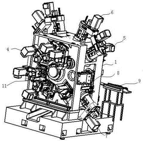
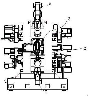
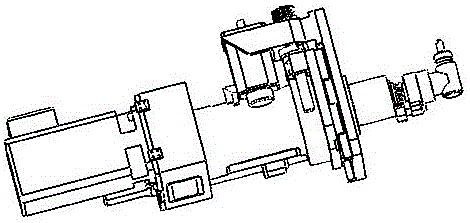
[0022] figure 1 It is a structural schematic diagram of the waterwheel type square body valve processing device of the present invention; figure 2 It is the front view of the waterwheel type square body valve processing device of the present invention; Figure 5 It is a schematic diagram of the connection between the turntable and the indexing system of the waterwheel type square valve processing device of the present invention.

[0023] See figure 1 , figure 2 and Figure 5 , the waterwheel type square body valve processing device provided by the present invention includes a bed 1, an indexing system 2, a turntable 3, a horizontal left power head 4, a horizontal right power head 5, an upper power head 6, and a lower power head 7 , blanking system 8, feeding system 9 and fixture 10; the indexing system 2 is connected with the turntable 3; the upp...


PUM


Abstract

The invention discloses a waterwheel type machining device for a cubical valve. The waterwheel type machining device for the cubical valve comprises a bed piece, wherein the bed piece is provided with a rotating table and multiple power heads; the centerlines of the main axes of the multiple power heads intersect at one point; the rotating table is connected with a graduation system and multiple clamping apparatuses; the centerlines, in four directions, of a work piece clamped by the clamping apparatuses are coincident with the centerlines of the main axes of four power heads; a YZ-axis power unit is arranged on a left-right side of the bed piece; the YZ-axis power unit is parallel to the mean surface of the rotating table; and a 90-degree angular head is adopted at the front end of YZ-axis power unit. According to the waterwheel type machining device for the cubical valve, through arranging the rotating table and the multiple power heads, of which the centerlines of the main axes intersect at one point, on the bed piece, the centerlines of the main axes of the multiple heads intersect at one point; the YZ-axis power unit for which the 90-dregreee angular head is adopted and the clamping apparatuses on the rotating table are cooperated; thus, the multi-station and multi-direction full automatic machining can be realized; further, the machining precision and the stability are higher; the production efficiency is higher; the integral structure is simple; and the manufacturing is convenient.

Description

technical field [0001] The invention relates to a square valve processing equipment, in particular to a water wheel type square valve processing device. Background technique [0002] At present, the square valve is an indispensable consumable product for the production of air conditioners, hardware fittings, etc. At present, the waterwheel processing machine can only process valve body parts in three directions, while the square valve has five processing directions, so it needs Two machines are required to complete the process. Quite a few manufacturers of square valves in China are still labor-intensive. Such companies use general-purpose machine tools to process valve bodies and need to replace various processes and fixtures, resulting in low efficiency, high labor costs, and poor processing accuracy and stability. Good guarantee. The cube valve has five directions, and there are external annular grooves, internal threads, external threads, through holes, etc., which req...

Claims


Application Information

Patent Timeline
IPC IPC(8): B23Q16/10B23Q3/08
CPCB23Q3/082B23Q16/10
Inventor 姜饶保冯本航赵计关
Owner 朗快智能科技(杭州)有限公司
Features
  • Generate Ideas
  • Intellectual Property
  • Life Sciences
  • Materials
  • Tech Scout
  • Unparalleled Data Quality
  • Higher Quality Content
  • 60% Fewer Hallucinations
Learn More