
Press-fitting detection head for clamp spring used for shaft

A detection head and indenter technology, which is applied in the field of circlip press assembly, can solve the problems of potential safety hazards, low work efficiency, and the inability to detect and judge whether the circlip press assembly of the shaft is qualified, etc., so as to reduce man-made omissions and ensure Improve assembly quality and improve work efficiency

Active Publication Date: 2016-10-12
HANGZHOU WOLEI INTELLIGENT TECH
View PDF7 Cites 7 Cited by
  • Summary
  • Abstract
  • Description
  • Claims
  • Application Information

AI Technical Summary

Problems solved by technology

[0002] The press-fit assembly of the circlip for the shaft is a very common part in the production and assembly of mechanical products (such as the assembly of auto parts). If there is a problem with the press-fit of the circlip, it will often affect the quality of the entire mechanical product and pose a safety hazard
Although the existing circlip press-fitting technology for shafts can complete the circlip press-fitting process, it is impossible to detect and judge whether the circlip press-fitting for shafts is qualified. The advanced assembly technology not only has low work efficiency, which affects the efficiency of production and assembly, but also is very inaccurate in visually checking whether the assembly is in place, and cannot guarantee the assembly quality

Method used


Image

  • Press-fitting detection head for clamp spring used for shaft
  • Press-fitting detection head for clamp spring used for shaft
  • Press-fitting detection head for clamp spring used for shaft

Examples


Embodiment Construction

[0011] The present invention and the technical solutions in the embodiments of the present invention will be clearly and completely described below in conjunction with the accompanying drawings.

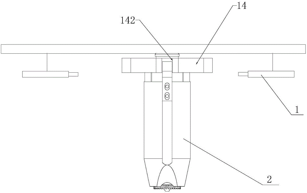
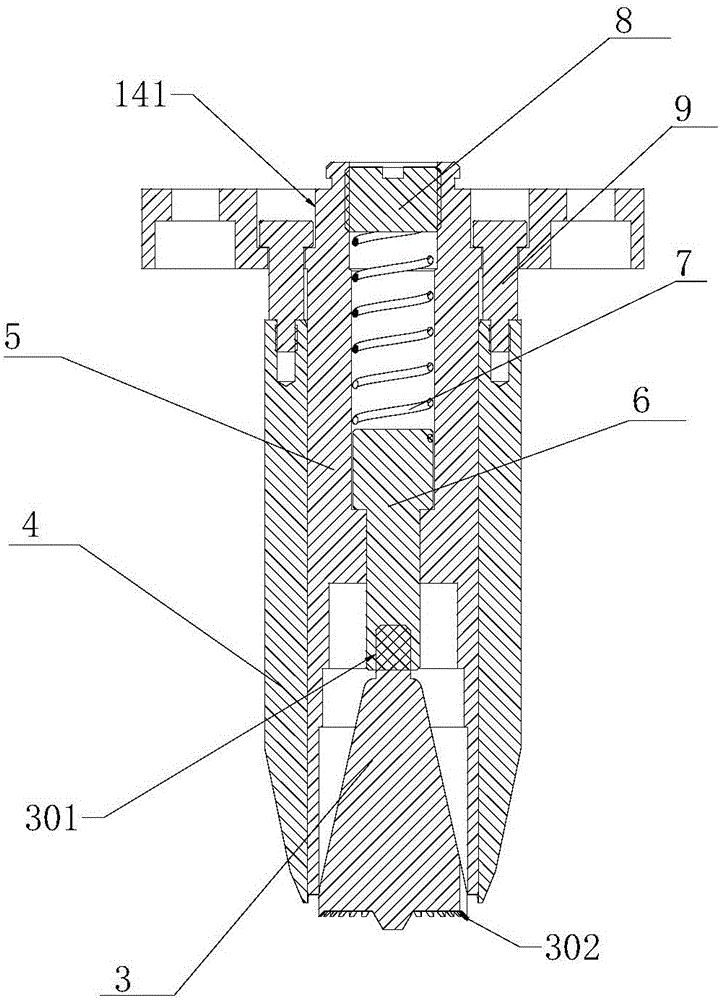
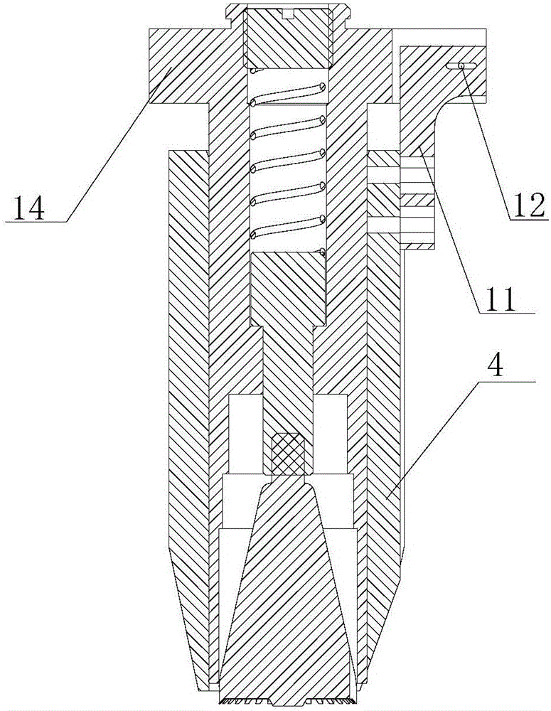
[0012] Such as figure 1 , 2 , Shown in 3, the present invention provides a kind of clamping spring pressure-mounted detection head for shaft, comprises pressure-fitted detection head inner core 5, compression spring 7, spring top 6, spring blocking block 8, circlip pressure head 3. The circlip pressure head 3 is in a conical structure, the conical bottom 302 is provided with teeth, the conical head 301 is connected to the spring top 6 by threads, the circlip pressure head 3 can be disassembled, and the other end of the spring top 6 is in contact with the compression spring 7, Surrounded by the inner core 5 of the press-fit test head, it moves up and down in the inner core 5 of the press-fit test head. The other end of the compression spring 7 is fixed by the spring block 8. The pro...


PUM


Abstract

The invention discloses a press-fitting detection head for a clamp spring used for a shaft. The press-fitting detection head comprises a clamp spring pressure head. Engagement teeth are arranged at the bottom of the clamp spring pressure head. A conical head is connected to a spring top head through a thread. The other end of the spring top head is in contact with a compression spring and moves vertically in the press-fitting detection head. The other end of the compression spring is fixed through a spring blocking block. An inner core of the press-fitting detection head is fixedly installed on the surface of a pressure head seat. The inner core of the press-fitting detection head is covered with a press-fitting detection head outer sleeve. Limiting screws and the press-fitting detection head outer sleeve can slide vertically in a bolt hole of the pressure head seat. A detection hole is formed in a detection block and the pressure head seat, and light rays of oppositely-radiating photoelectric sensors pass through the detection hole. By means of the press-fitting detection head, the clamp spring used for the shaft can be conveniently and rapidly pressed into a designated position, meanwhile, the abnormity state of clamp spring press-fitting can be detected, the working efficiency is improved, the step that whether the clamp spring is arranged in place in a press-fitting manner or not is checked in a manual visual manner is omitted, manual omissions are reduced, and the assembly quality of the clamp spring is ensured.

Description

technical field [0001] The invention relates to a clamp spring press-fit assembly technology, in particular to a clamp spring press-fit detection head for a shaft. Background technique [0002] The press-fitting and assembly of the shaft circlip is a very common part in the production and assembly of mechanical products (such as the assembly of auto parts). If there is a problem with the press-fitting of the circlip, it will often affect the quality of the entire mechanical product and pose a safety hazard. Although the existing circlip press-fitting technology for shafts can complete the circlip press-fitting process, it is impossible to detect and judge whether the circlip press-fitting for shafts is qualified. Advanced assembly technology not only has low work efficiency, which affects the efficiency of production and assembly, but also is very inaccurate in visually checking whether the assembly is in place, and the assembly quality cannot be guaranteed. Contents of th...

Claims


Application Information

Patent Timeline
Patent Type & Authority Applications(China)
IPC IPC(8): B25B27/20
CPCB25B27/20
Inventor 陆艺李静伟赵晨馨郭斌范伟军罗哉胡晓峰
Owner HANGZHOU WOLEI INTELLIGENT TECH
Learn More