Fan-shaped clamp and method for reducing blade assembly welding deformation

A welding deformation and blade technology, applied in welding equipment, manufacturing tools, auxiliary devices, etc., can solve the problems of position deviation, data deviation, and the position accuracy of the outer assembly part of the edge plate cannot meet the requirements, so as to improve and reduce the pass rate. The effect of welding deformation and the effect of ensuring assembly quality

Active Publication Date: 2018-05-15
SHENYANG LIMING AERO-ENGINE GROUP CORPORATION
View PDF7 Cites 13 Cited by
  • Summary
  • Abstract
  • Description
  • Claims
  • Application Information

AI Technical Summary

Problems solved by technology

However, due to the large deformation phenomenon of each individual blade in the process of being welded into the segment assembly, the flow channel position of the segment assembly deviates greatly from the data required by the process, so that the processed parts after combined welding The position accuracy of the outer assembly part of the edge plate cannot meet the requirements
For a period of time, due to the problems in the welding process of the sector components, the warpage and deformation of the reference outer circular surface and the end face reference plane surface formed by the welding of each single blade reached more than 0.5mm, while the benchmark of the sector components The datum plane of the outer circular surface and the end face is not only the processing datum of the flow channel of each single blade, but also the machining datum of the outer assembly part of the edge plate of the segment assembly. Such a large deformation of the datum plane will inevitably cause position deviation between the flow passage and the assembly part.

Method used


Image

  • Fan-shaped clamp and method for reducing blade assembly welding deformation
  • Fan-shaped clamp and method for reducing blade assembly welding deformation

Examples


Embodiment Construction

[0025] The present invention will be described in further detail below in conjunction with embodiment.

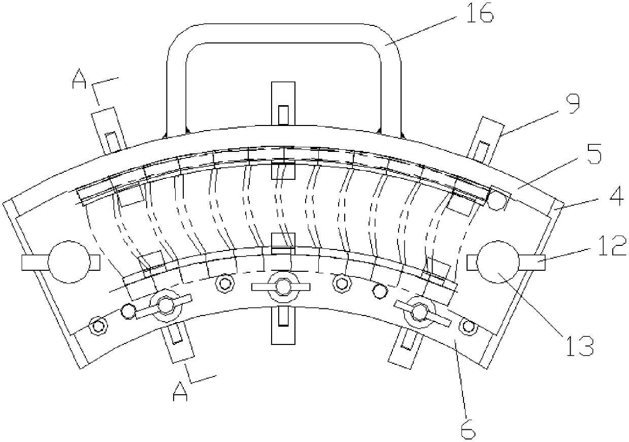
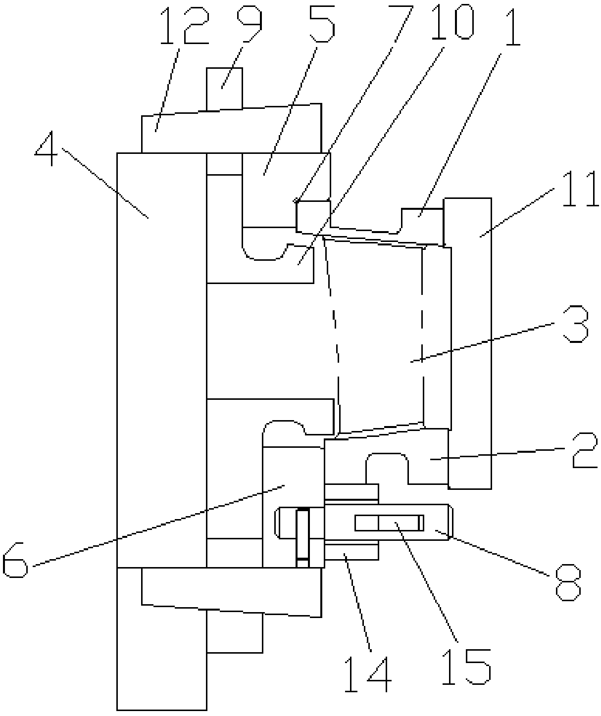
[0026] according to Figure 1 ~ Figure 2 As shown, the present invention provides a fan-shaped clamp for reducing the welding deformation of the blade assembly, which is used to clamp the blade. The blade is composed of an upper edge plate 1, a lower edge plate 2 and a blade body 3 between them. The fixture includes: a bottom plate 4, the bottom plate 4 is a fan-shaped bottom plate, a handle 16 is provided on one side of the bottom plate 4, which is convenient for taking and placing the fixture, and an upper edge plate positioning block is arranged on the bottom plate 4 along the horizontal direction 5 and the lower edge plate positioning block 6, the upper edge plate positioning block 5 and the lower edge plate positioning block 6 are both arc-shaped structures, and the upper edge plate positioning block 5 and the lower edge plate positioning block 6 face the end faces of ...


PUM


Abstract

The invention relates to a fan-shaped clamp and method for reducing blade assembly welding deformation. The clamp comprises a base plate, the base plate is provided with an upper edge plate positioning block and a lower edge plate positioning block, a positioning pin is arranged on the lower edge plate positioning block, circumferential pressing blocks are inserted into the upper edge plate positioning block and the lower edge plate positioning block, hook-type parts are arranged at one ends of the circumferential pressing blocks, first locking devices are arranged on the circumferential pressing blocks, an upper pressing block is arranged at the upper end of the base plate, and a second locking device is arranged on the upper pressing block. After welding is carried out through the clampand method, the welding deformation influences are greatly reduced, a reference surface formed after welding is used for appropriately grinding treatment, a good standard is machined through a fan-shaped section assembly edge plate part, the deformation condition does not exist after a fan-shaped section assembly edge plate is machined, the assembly quality is better guaranteed, the position accuracy of a runner part better meets the assembly requirement, and the yield of a welded assembly is greatly improved.

Description

Technical field: [0001] The invention relates to the technical field of blade component welding, in particular to a fan-shaped fixture and a method for reducing the welding deformation of a blade component. Background technique: [0002] In the original welding of rectifier components, due to the unreasonable welding method and the measures to prevent deformation, the components after welding have a large deformation, which affects the guarantee of the processing dimensional accuracy of subsequent components, and brings great difficulties to assembly. affect engine performance. [0003] At present, many rectifying blades of aero-engines work in the form of segment assembly structure. The segment assembly is welded by combining multiple single blades. The flow path of each single blade has been processed, and the segment assembly is welding Finally, it is necessary to complete the processing of the outer assembly part of the flange to ensure that the flow channel and the out...

Claims


Application Information

Patent Timeline
Patent Type & Authority Applications(China)
IPC IPC(8): B23K3/08B23K1/008B23K1/20
CPCB23K1/0008B23K1/008B23K1/20B23K3/087
Inventor 刘随建杜静李美荣高见王荣
Owner SHENYANG LIMING AERO-ENGINE GROUP CORPORATION
Why Eureka
Try Eureka