Eureka AIR delivers breakthrough ideas for toughest innovation challenges, trusted by R&D personnel around the world.

Asynchronous die cutting method and asynchronous die cutting machine for achieving method

A die-cutting machine and die-cutting technology, applied in the direction of metal processing, etc., can solve the problems of increased labor force, waste of die-cutting layer materials, and reduced production efficiency, and achieve low manual participation, easy processing and transformation, and improved production efficiency. Effect

Active Publication Date: 2016-10-12
浙江川日机械有限公司
View PDF5 Cites 7 Cited by
  • Summary
  • Abstract
  • Description
  • Claims
  • Application Information

AI Technical Summary

Problems solved by technology

[0004] However, when the die-cut layer does not completely cover the base layer or the die-cut products with simple stripes are produced, a die-cut layer cutting mechanism is generally added after the conventional size cutting machine is attached to the roller group, and the die-cut layer in the blank area is processed. Cutting, and then use the method of manually tearing off the blank die-cut layer to achieve the purpose of producing this type of product. This method of production causes a lot of waste of die-cut layer materials, and the labor force is also greatly increased. Labor costs, reducing production efficiency and wasting resources

Method used


Image

  • Asynchronous die cutting method and asynchronous die cutting machine for achieving method
  • Asynchronous die cutting method and asynchronous die cutting machine for achieving method
  • Asynchronous die cutting method and asynchronous die cutting machine for achieving method

Examples


Embodiment Construction

[0030] In the following, a specific embodiment of the present invention will be described by taking die-cutting materials in which the die-cutting layers are equidistantly distributed on the base layer as an example.

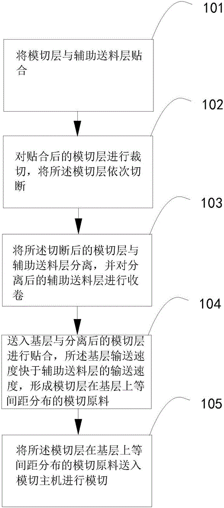
[0031] The asynchronous die-cutting method of the present embodiment comprises the following steps:

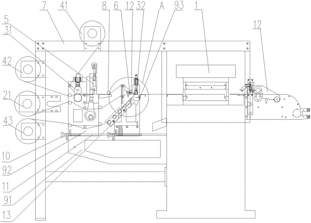
[0032] Step 101: sending the die-cutting layer 14 and the auxiliary feeding layer 15 into the first bonding roller group 31 for lamination, so that the die-cutting layer 14 and the auxiliary feeding layer 15 form a bonding that is easier to peel off;

[0033] Step 102: sending the laminated die-cut layer 14 into the die-cut layer cutting mechanism 5 for cutting, and sequentially cutting the die-cut layer 14 pasted on the upper layer of the auxiliary feeding layer 15;

[0034] Step 103: Send the cut die-cutting layer 14 and auxiliary feeding layer 15 into the die-cutting layer and auxiliary feeding layer separation mechanism 6 for separation, and use the auxiliar...


PUM


Abstract

The invention relates to an asynchronous die cutting method and an asynchronous die cutting machine for achieving the method. The asynchronous die cutting method comprises the following steps that a die cutting layer and an auxiliary feeding layer are laminated; the laminated die cutting layer is sequentially cut off; the cut die cutting layer is separated from the auxiliary feeding layer, and the separated auxiliary feeding layer is wound; a base layer is fed to be laminated with the separated die cutting layer, the conveying speed of the base layer is higher than that of the auxiliary feeding layer, and die cutting raw materials, distributed on the base layer at equal intervals, of the die cutting layer are formed; and the die cutting raw materials, distributed on the base layer at equal intervals, of the die cutting layer are fed into a die cutting main engine to be subjected to die cutting. The asynchronous die cutting machine for achieving the method comprises the die cutting main engine, a rack, discharging shafts, a laminating mechanism, a cutting mechanism for the die cutting layer, a mechanism for separating the die cutting layer from the auxiliary feeding layer and material receiving shafts. The asynchronous die cutting method and the asynchronous die cutting machine for achieving the method are efficient, rapid and capable of saving materials.

Description

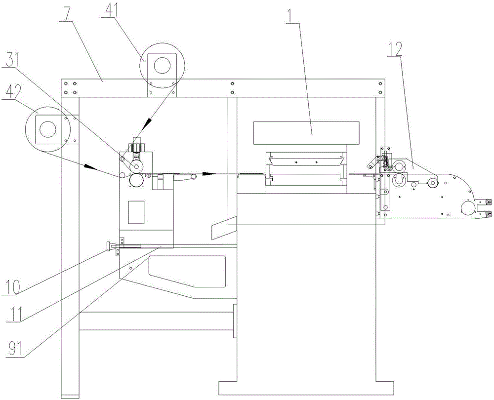
technical field [0001] The invention relates to a die-cutting method and a die-cutting machine, in particular to an asynchronous die-cutting method and an asynchronous die-cutting machine for realizing the method, and belongs to the technical field of punching and cutting. Background technique [0002] The working principle of the die-cutting machine is to use a die-cutting knife, a steel knife, a metal mold, and a steel wire to apply a certain pressure through the embossing plate to roll and cut the printed matter or cardboard into a certain shape, and cut the entire printed matter into a single graphic. The product is called die-cutting. If one kind of base material is used to laminate another base material, it is called lamination. Excluding the rest of the original product is called waste discharge. The above can be collectively referred to as die-cutting technology. Asynchronous die-cutting refers to It is a process in which the die-cutting layer used for die-cutting an...

Claims


Application Information

Patent Timeline
IPC IPC(8): B26F1/38B26D7/00B26D7/32
CPCB26D7/00B26D7/32B26D7/325B26D2007/322B26F1/38
Inventor 吴星荣吴星钿
Owner 浙江川日机械有限公司
Why Eureka
Eureka Blog
Learn More