
Electric car air conditioner system and electric car with same

A technology for air conditioning systems and electric vehicles, applied in vehicle components, air handling equipment, heating/cooling equipment, etc., can solve problems such as affecting the reliability of system operation, increasing the compression ratio, affecting the cruising range of electric vehicles, etc., to improve the system The effect of improving reliability, heat exchange efficiency, and improving low temperature environment suitability

Active Publication Date: 2016-10-12
GREE ELECTRIC APPLIANCES INC
View PDF7 Cites 9 Cited by
  • Summary
  • Abstract
  • Description
  • Claims
  • Application Information

AI Technical Summary

Problems solved by technology

[0002] In the low temperature environment in winter, the air conditioning system of pure electric vehicles cannot use the combustion waste heat of engine cooling water to operate. At present, electric vehicle heating in winter mainly adopts PTC electric heating, but PTC electric heating requires a large amount of electric energy stored in electric vehicle batteries, which greatly affects The cruising range of electric vehicles; while using traditional air-conditioning systems, as the outside temperature decreases, the heating capacity and heating efficiency of the air-conditioning system will drop rapidly, and the compression ratio will increase, which will affect the reliability of the system.

Method used


Image

  • Electric car air conditioner system and electric car with same
  • Electric car air conditioner system and electric car with same
  • Electric car air conditioner system and electric car with same

Examples


Embodiment Construction

[0020] In the description of the present invention, it should be understood that the orientation or positional relationship indicated by the terms "upper", "lower", "side", and "bottom" are based on the orientation or positional relationship shown in the drawings, and are only In order to facilitate the description of the present invention and simplify the description, it does not indicate or imply that the device or element referred to must have a specific orientation, be constructed and operated in a specific orientation, and thus should not be construed as limiting the present invention.

[0021] In addition, the terms "first", "second", and "third" are used for descriptive purposes only, and cannot be interpreted as indicating or implying relative importance or implicitly specifying the quantity of the indicated technical features. Thus, a feature defined as "first", "second" and "third" may explicitly or implicitly include one or more of these features.

[0022] In the de...


PUM


Abstract

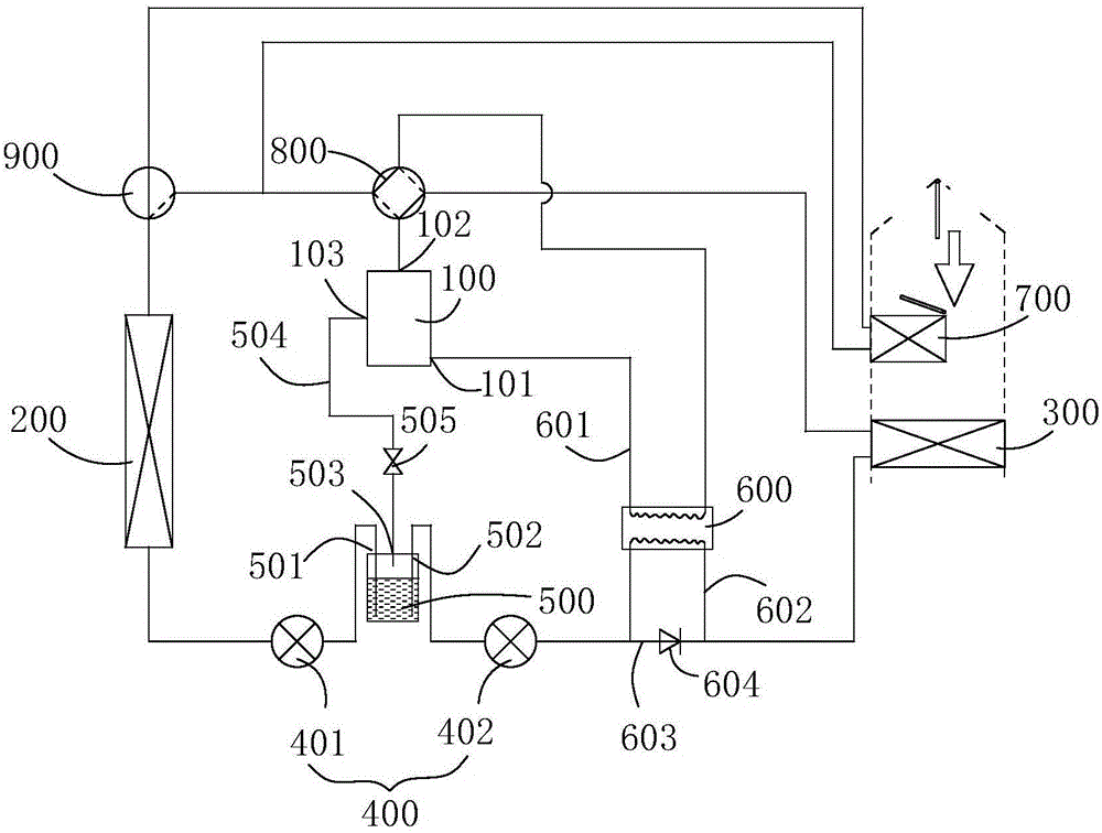
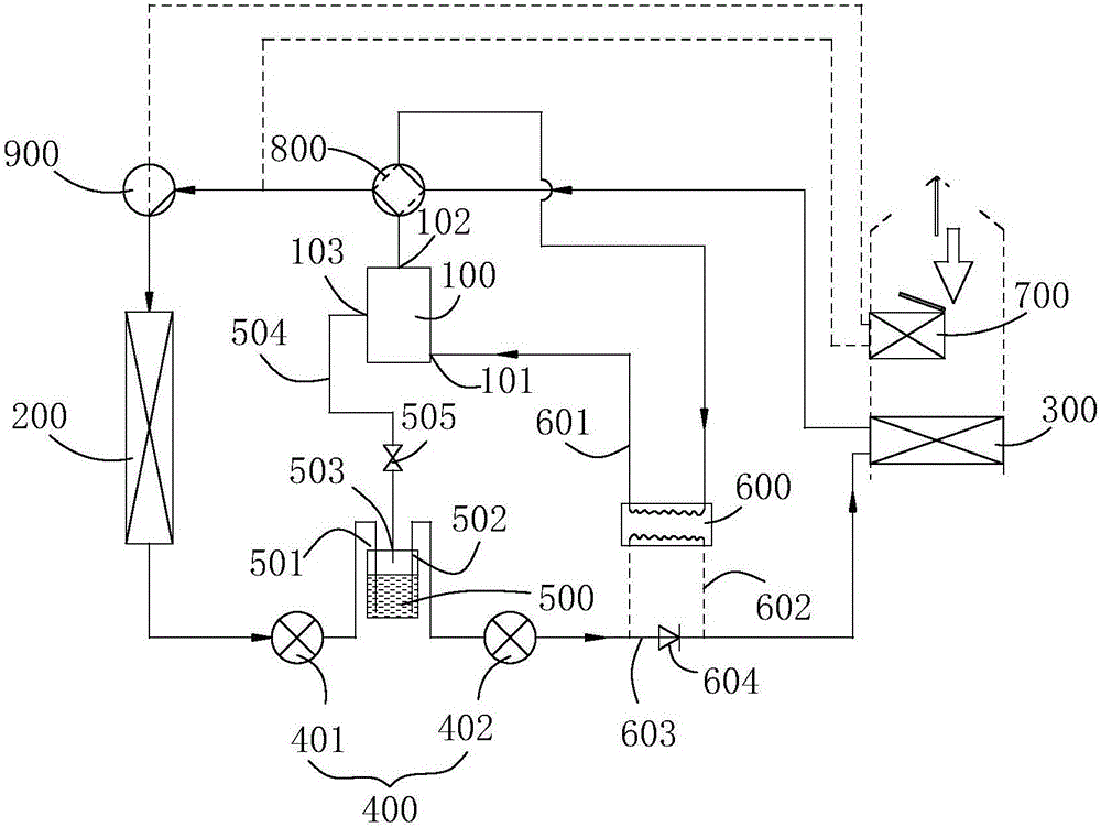
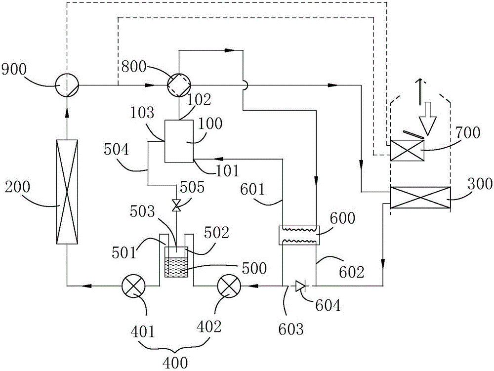
The invention discloses an electric car air conditioner system which comprises a compressor, a car interior main heat exchanger, a throttling device and a car exterior heat exchanger, and further comprises a flash vessel and a regenerator, wherein the compressor, the car interior main heat exchanger, the throttling device and the car exterior heat exchanger are sequentially connected; the flash vessel is arranged on a connection pipeline between the car exterior heat exchanger and the car interior main heat exchanger and selectively communicates with a compressor air supply opening through an air supply pipeline; and the regenerator is arranged between the compressor and the car interior main heat exchanger and used for conducting heat exchange on coolants entering an air suction opening of the compressor and coolants at an outlet of the car interior main heat exchanger. Enhanced vapor injection is conducted on the compressor through the flash vessel, the regenerator is arranged between the air suction opening of the compressor and the car interior main heat exchanger, the degree of supercooling at an outlet of a condenser and the degree of air suction superheating of the compressor can be effectively improved under the working condition of low temperature heating, and accordingly the heating capacity of the system is improved, liquid impact of the compressor is prevented, and the system reliability is improved. In addition, the invention provides an electric car with the electric car air conditioner system. The driving mileage can be effectively prolonged.

Description

technical field [0001] The invention relates to the field of electric vehicles, in particular to an electric vehicle air conditioning system and an electric vehicle using the same. Background technique [0002] In the low temperature environment in winter, the air conditioning system of pure electric vehicles cannot use the combustion waste heat of engine cooling water to operate. At present, electric vehicle heating in winter mainly adopts PTC electric heating, but PTC electric heating requires a large amount of electric energy stored in electric vehicle batteries, which greatly affects The cruising range of electric vehicles; while using traditional air-conditioning systems, as the outside temperature decreases, the heating capacity and heating efficiency of the air-conditioning system will drop rapidly, and the compression ratio will increase, which will affect the reliability of the system operation. Contents of the invention [0003] An object of the present invention...

Claims


Application Information

Patent Timeline
Patent Type & Authority Applications(China)
IPC IPC(8): B60H1/00B60H1/22
CPCB60H1/00392B60H1/22
Inventor 吴会丽李潇李俊峰
Owner GREE ELECTRIC APPLIANCES INC
Learn More