

Dynamic cable seal limit anchorage structure
An anchoring structure and dynamic cable technology, applied in cable laying ships, cable installation, ground cable installation, etc., can solve problems such as delay in construction period, and achieve the effects of convenient transportation, reduction of installation cost, and improvement of installation efficiency
- Summary
- Abstract
- Description
- Claims
- Application Information
AI Technical Summary
Problems solved by technology
Method used
Image


Examples
Embodiment Construction
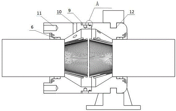
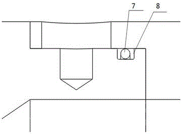
[0023] Such as Figure 1 to Figure 5 A dynamic cable seal position-limiting anchoring structure shown includes a front anchor 1 and a rear anchor 2, the front anchor 1 and the rear anchor 2 are provided with cavities and one end is provided with a through hole, the The through hole and the cavity communicate with each other, the front anchor 1 and the rear anchor 2 are connected to each other and the two cavities are connected to each other, and the junction of the front anchor 1 and the rear anchor 2 is provided with a sealing groove 8, so The sealing groove 8 is provided with a first sealing ring 7, and the ends of the front anchor 1 and the rear anchor 2 are provided with a cover plate 3. Between the front anchor 1, the rear anchor 2 and the cover plate 3 A second sealing ring 6 is provided.
[0024] As a further optimization of the above technical solution:
[0025] Further, the first sealing ring 7 is an O-ring.
[0026] Further, the second sealing ring 6 is a fluorine...
PUM
 Abstract
Description
Claims
Application Information