Pneumatic conveyor

A technology of pneumatic conveying and air compressor, which is applied in the direction of conveyors, conveying bulk materials, transportation and packaging, etc. It can solve the problems of lack of air temperature control, etc., and achieve the effect of simple and practical structure, stable pressure and waste reduction

Pending Publication Date: 2016-10-12
ANHUI ZEJIAYE POWDER ENG
View PDF0 Cites 2 Cited by
  • Summary
  • Abstract
  • Description
  • Claims
  • Application Information

AI Technical Summary

Problems solved by technology

[0003] The technical problem to be solved by the present invention is: aiming at the problem that the existing pneumatic conveyor mentioned in the background technology, especially the pressure-feeding pneumatic conveyor does not have the problem of temperature control of the air, the present invention provides an air temperature controllable and Pneumatic conveyor with small air pressure fluctuation

Method used


Image

  • Pneumatic conveyor
  • Pneumatic conveyor
  • Pneumatic conveyor

Examples


Embodiment Construction

[0019] Specific embodiments of the present invention will be described in detail below in conjunction with the accompanying drawings.

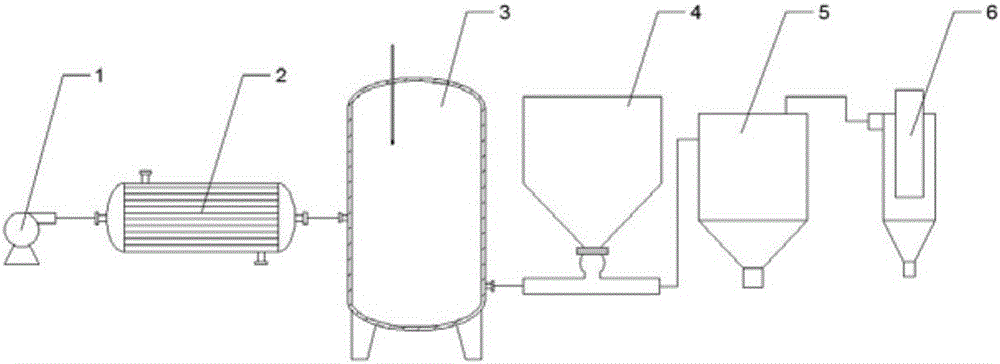
[0020] like figure 1 , figure 2 , image 3 A pneumatic conveyor shown includes an air compressor (1), a heat exchanger (2), a storage tank (3), a feeder (4), a material separator (5), and a dust collector (6); After the air compressor (1) compresses the air, it presses the compressed air into the heat exchanger (2). After the heat exchanger (2) heats up or cools down the compressed air, the compressed air enters the feeder (4) to bring the material into the material separation The material separator (5) and the material separator (5) separate the material from the waste gas, and the waste gas is discharged into the dust collector (6) for dust removal.

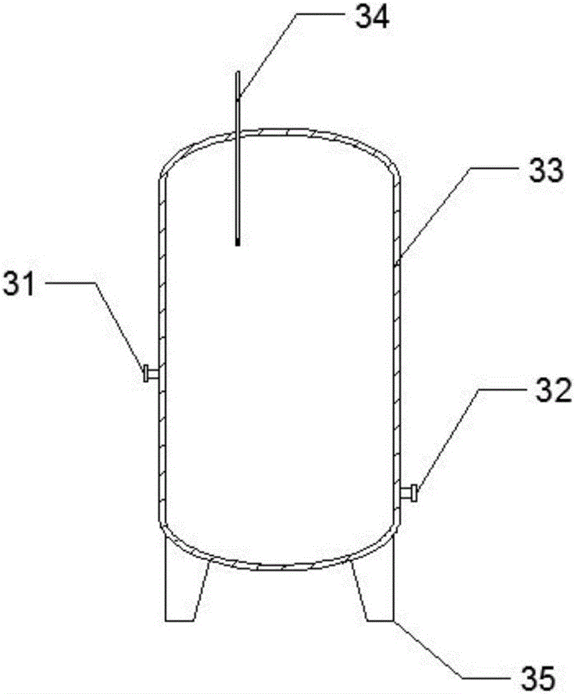
[0021] The storage tank (3) includes a tank body (33), legs (35), air inlet (31), air outlet (32) and a thermometer (34); Material.

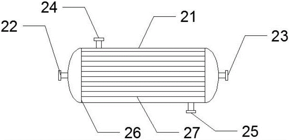
[0022] The heat exchanger (2) is a shell-and-tube hea...


PUM


Abstract

A pneumatic conveyor belongs to the field of pneumatic conveying equipment. Aiming at the problem that existing pneumatic conveyors, especially pressure-feeding pneumatic conveyors, do not have the function of controlling air temperature, the present invention adopts the following scheme: after the air compressor compresses the air, Press the compressed air into the heat exchanger, after the heat exchanger heats up or cools down the compressed air, the compressed air enters the feeder to bring the material into the material separator, the material separator separates the material from the waste gas, and the waste gas is discharged into the dust collector for dust removal; Based on the above solution, the present invention realizes the control of air temperature, and is suitable for conveying temperature-sensitive materials or materials with special temperature requirements.

Description

technical field [0001] The invention belongs to the field of pneumatic conveying equipment, and in particular relates to a pneumatic conveying machine. Background technique [0002] The pneumatic conveyor is to put the material in the air with a certain speed, transport it to the unloading point through the pipeline and then separate the material, so as to achieve the purpose of conveying the material. The invention relates to a pressure-feeding type pneumatic conveyor. The existing pressure-feeding type pneumatic conveyor does not have the ability to control the air temperature, and cannot transport some materials that are sensitive to temperature or have special requirements on temperature. Contents of the invention [0003] The technical problem to be solved by the present invention is: aiming at the problem that the existing pneumatic conveyor mentioned in the background technology, especially the pressure-feeding pneumatic conveyor does not have the problem of tempera...

Claims


Application Information

Patent Timeline
Patent Type & Authority Applications(China)
IPC IPC(8): B65G53/36B65G53/66B65G53/34
CPCB65G53/36B65G53/34B65G53/66
Inventor 陈泽民
Owner ANHUI ZEJIAYE POWDER ENG
Why Eureka
Try Eureka