Supercharge Your Innovation With Domain-Expert AI Agents!

Weft yarn detection device for air-jet loom

A technology of air-jet loom and detection device, applied in looms, textiles, textiles and papermaking, etc., can solve problems such as difficulty in checking the state of weft yarns

Active Publication Date: 2017-08-25
TOYOTA IND CORP
View PDF1 Cites 1 Cited by
  • Summary
  • Abstract
  • Description
  • Claims
  • Application Information

AI Technical Summary

Problems solved by technology

However, in woven fabric structures where the top warp yarns are continuous (such as satin fabrics), it is sometimes difficult to check the condition of the weft yarns in the warp shed using a stroboscope

Method used


Image

  • Weft yarn detection device for air-jet loom
  • Weft yarn detection device for air-jet loom
  • Weft yarn detection device for air-jet loom

Examples


no. 1 example

[0031] A first embodiment of the invention will now be referred to Figure 1-8 to describe.

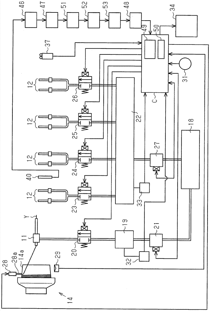
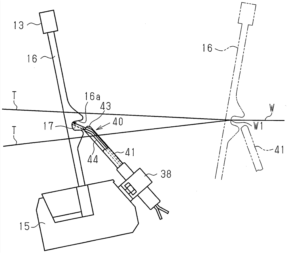
[0032] like figure 1 and figure 2 Shown, air-jet loom comprises main nozzle 11 for weft insertion, a plurality of auxiliary nozzles 12 for weft insertion, reed 13 (shown in figure 2 ) and weft measuring and storage device 14 (shown in figure 1 middle). like figure 2 As shown, the main nozzle 11 , the auxiliary nozzle 12 and the reed 13 are fixed to the sley 15 . The reed 13 comprises teeth 16 arranged in the weft insertion direction. Each tooth 16 has a guide recess 16a. The guide recesses 16a of the teeth 16 form the reed channels 17 .

[0033] like figure 1 As shown, the main nozzle 11 is connected via piping to a main nozzle tank 19 for the main nozzle 11 . The main nozzle tank 19 is connected to the source pressure tank 18 . The electromagnetic switch valve 20 is provided between the main nozzle 11 and the main nozzle tank 19 . The jet of pressurized air for weft...

no. 2 example

[0063] will now refer to Figures 9 to 16 A second embodiment is described. The second embodiment differs from the first embodiment in that the estimating section (CPU 49) does not estimate the time point of maximum tension as the time when the output signal value from the signal processor (band pass filter 47) drops to a predetermined threshold value. time point, but the time point of maximum tension is estimated by the integration method. Components that are the same as or similar to those of the first embodiment will not be described again.

[0064] like Figure 9 As shown, a full-wave rectifier 51 , an averaging circuit 52 and an integrating circuit 53 are provided between the band-pass filter 47 and the A / D converter 48 as hardware components. A full-wave rectifier 51 , an averaging circuit 52 , and an integrating circuit 53 are arranged in this order from the band-pass filter 47 .

[0065] Figure 10 Changes in the crank angle 0° signal, the output signal of the ban...


PUM


Abstract

The invention relates to a weft detection apparatus for an air-jet weaving machine. The weft detection apparatus comprises a main nozzle for guiding weft, an auxiliary nozzle for guiding weft, a reed comprising a reed channel, a sensor for detecting weft passing through a warp shuttle port arranged at the reed channel and located in a region between the center of the reed channel and the main nozzle, a signal processor and an estimation portion. The signal processor receives an output signal from the sensor and allows an output signal frequency in a range of 0.5-20 kHz to pass through. The estimation portion estimates a time point of a maximum tension of the weft based on the value of the output signal from the signal processor.

Description

technical field [0001] The invention relates to a weft detection device for an air-jet loom. More specifically, the present invention relates to a weft yarn detection device that detects the state of a weft yarn introduced through a channel in a reed by means of air jets from main and auxiliary nozzles. Background technique [0002] In air-jet looms of this type, the state of the weft yarn during weft insertion largely depends on the pressure setting of the pressurized air. Generally, Japanese Laid-Open Patent Publication No. 4-241135 discloses a weft insertion pressure control device for an air-jet loom configured to improve the consumption efficiency of jet fluid while eliminating weft yarn slack in the second half of weft insertion and Reduces missing wefts in weft insertion. The control device disclosed above detects the weft yarn unwinding end time and the weft yarn front end arrival time in the weft yarn measurement and storage device, and controls the injection pres...

Claims


Application Information

Patent Timeline
Patent Type & Authority Patents(China)
IPC IPC(8): D03D47/30
CPCD03D47/3073
Inventor 牧野洋一高木信次荒井隆二铃木藤雄鹫见和正
Owner TOYOTA IND CORP
Features
  • R&D
  • Intellectual Property
  • Life Sciences
  • Materials
  • Tech Scout
  • Unparalleled Data Quality
  • Higher Quality Content
  • 60% Fewer Hallucinations
Learn More