A top handle device for an electric iron

An electric iron and handle technology, which is applied to hand irons, washing devices, textiles and paper making, etc., can solve the problems of inconvenient control of steam volume and control method, increased processing and production difficulty, complicated assembly and maintenance, etc. The effect of batch flow production, reducing processing difficulty, and increasing steam and water volume

Active Publication Date: 2018-04-03
SHANGHAI WEIMAO ELECTRONICS
View PDF6 Cites 0 Cited by
  • Summary
  • Abstract
  • Description
  • Claims
  • Application Information

AI Technical Summary

Problems solved by technology

With the wide application of steam spray electric irons, it is found in the actual production and use process that the structure of the steam spray electric irons in the prior art is generally very complicated, especially the design of the various parts of the handle, which not only makes the processing And the production difficulty increases and the production cost increases, and the assembly and maintenance are also very cumbersome. More importantly, the handles of the current prior art are generally designed with the control switch above it, which requires two hands to control at the same time or the thumb to operate. Therefore, it is very inconvenient to control the amount of steam and the control method, especially when you need to iron many different pieces of clothes at one time, and regardless of the control accuracy of the thumb or the inconvenience of requiring two hands to control at the same time, only Because long-term control and adjustment will make the user's fingers very tired, and even cramps or spasms.

Method used


Image

  • A top handle device for an electric iron
  • A top handle device for an electric iron

Examples


Embodiment Construction

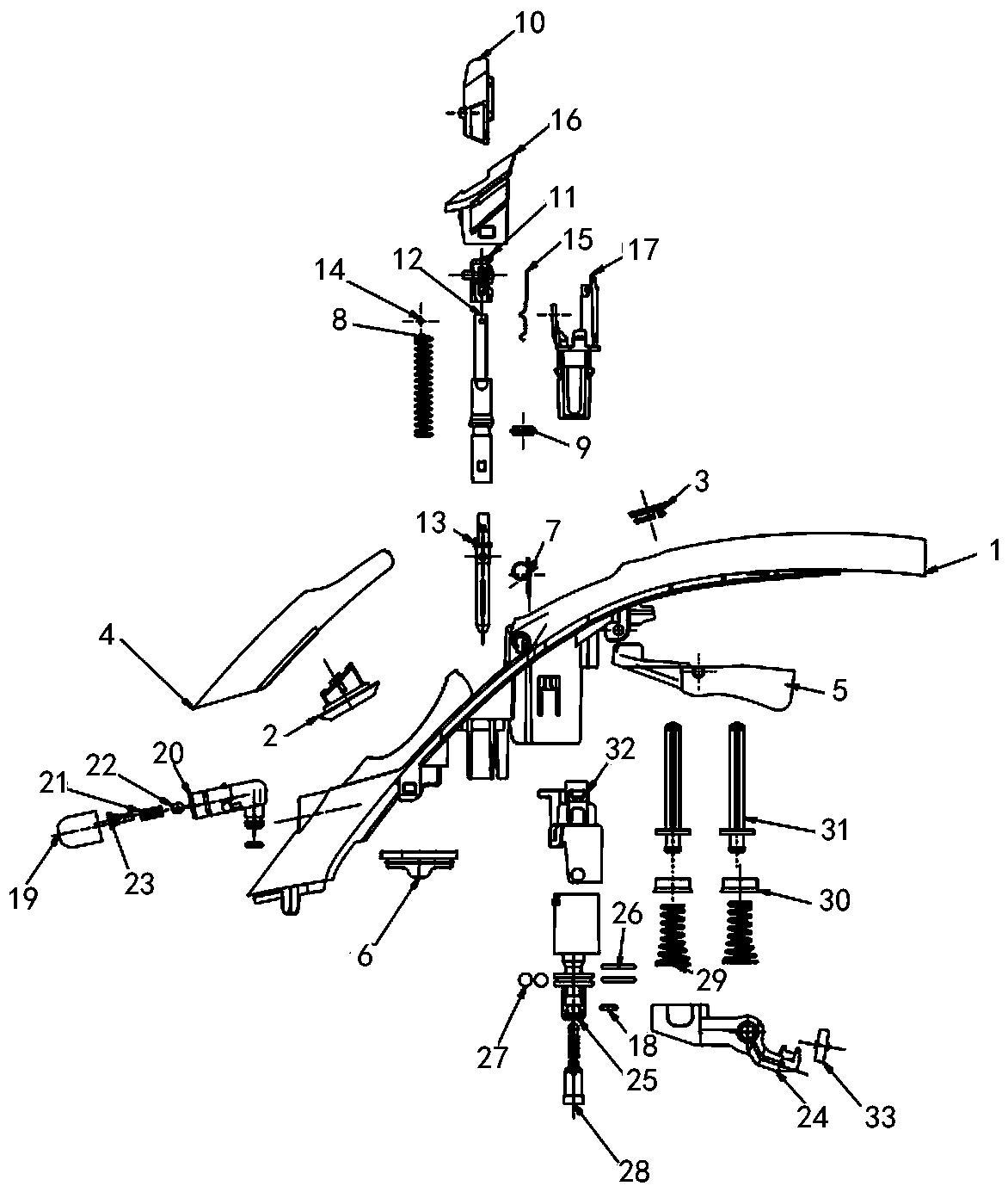
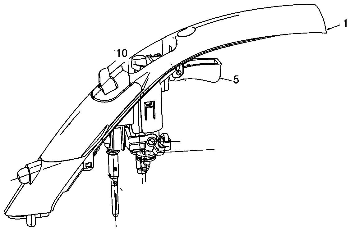
[0036] The technical solutions of the present invention will be clearly and completely described below in conjunction with the accompanying drawings. Apparently, the described embodiments are some of the embodiments of the present invention, but not all of them. Based on the embodiments of the present invention, all other embodiments obtained by persons of ordinary skill in the art without making creative efforts belong to the protection scope of the present invention.

[0037] In the description of the present invention, it should be noted that the terms "center", "upper", "lower", "left", "right", "vertical", "horizontal", "inner", "outer" etc. The indicated orientation or positional relationship is based on the orientation or positional relationship shown in the drawings, and is only for the convenience of describing the present invention and simplifying the description, rather than indicating or implying that the referred device or element must have a specific orientation, ...


PUM


Abstract

The invention provides a novel electric iron top handle device. The electric iron top handle device comprises an arc-shaped installation handle, a spray assembly, a movable plate assembly, a steam switch assembly and a control button assembly; the spray assembly comprises a spray body, a spray mushroom ball, a spray spring, a spray insert and a spray cover which are sequentially assembled from right to left; the movable plate assembly comprises a movable plate and a movable plate sealing gasket; the steam switch assembly comprises a shaft pin, a shaft support body, a shaft switch guide part, a shaft switch, a shaft sealing gasket arranged in the middle of the side face of the shaft support body, a shaft spring arranged on the upper portion of the side face of the shaft support body, a metal shaft arranged at the top end of the shaft support body, a shaft lock blade installed on the right side face of the shaft switch guide part and a shaft shell; the control button assembly comprises a pump cover, a pump rod, a pump nut, a pump spring, a steel ball, a pump shell and a pump switch. According to the electric iron top handle device, the steam amount and the water amount of an electric iron are increased, accurate control over the control switch is improved, the processing difficulty is reduced, batch continuous production is achieved, and the material cost and the assembly cost are both reduced.

Description

technical field [0001] The invention relates to the field of mechanical structures, in particular to a top handle device of an electric iron. Background technique [0002] An electric iron is a tool for flattening clothes and fabrics, and its power is generally between 300-1000W. Its types can be divided into: ordinary type, temperature adjustment type, steam spray type and so on. Among them, the ordinary type electric iron is simple in structure, cheap in price, and convenient to manufacture and maintain. The temperature-regulating electric iron can automatically adjust the temperature in the range of 60-250 ℃, and automatically cut off the power supply, and can be ironed at a suitable temperature according to different clothing materials, which saves electricity compared with the ordinary type. The steam spray type electric iron not only has the function of temperature adjustment, but also can generate steam, and some are also equipped with a spray device, so the trouble...

Claims


Application Information

Patent Timeline
Patent Type & Authority Patents(China)
IPC IPC(8): D06F75/34D06F75/10
CPCD06F75/10D06F75/34
Inventor 周豪良
Owner SHANGHAI WEIMAO ELECTRONICS
Why Eureka
Try Eureka