Anti-collision high elastic support in horizontal direction

A horizontal, anti-collision technology, applied in bridge parts, bridges, buildings, etc., can solve the problems of small elastic deformation, large size, small bearing capacity of a single butterfly spring, etc., and achieve increased bearing capacity and large elastic support. effect of action

Active Publication Date: 2018-05-22
BEIJING TIEKE SHOUGANG RAIL TECH CO LTD
View PDF8 Cites 0 Cited by
  • Summary
  • Abstract
  • Description
  • Claims
  • Application Information

AI Technical Summary

Problems solved by technology

[0003] At present, some high-elastic bearings with small bearing capacity use butterfly springs as elastic elements. Although assembling multiple butterfly springs can improve their overall bearing capacity and elastic deformation, due to the These features: a single butterfly spring has small bearing capacity and small elastic deformation. For example, a butterfly spring with a diameter of 250mm has a bearing capacity of only about 25 tons and a small elastic deformation. If you want to obtain a bearing capacity exceeding 1,000 tons, A highly elastic support with an elastic deformation of more than 20mm needs to assemble many butterfly springs, which will make the assembled size too large to be installed, the structure will be very complicated, and the cost will be high, so it is not feasible
[0004] To sum up, there is no elastic bearing with both large bearing capacity and large elastic deformation at present.

Method used


Image

  • Anti-collision high elastic support in horizontal direction
  • Anti-collision high elastic support in horizontal direction

Examples


no. 1 example

[0066] In the first embodiment of the present invention, the sum of the depths of the first groove and the second groove of the liner 4 does not exceed half of the thickness of the liner 4 .

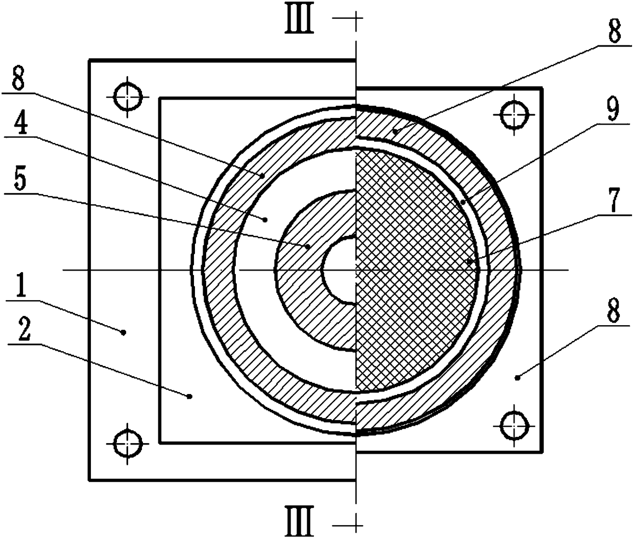
[0067] In a preferred embodiment of the present invention, wherein, the outer peripheral wall of the elastic plate 7, the force diffusion plate 6 and / or the liner 4 is in abutment contact with the inner peripheral wall of the accommodation space of the bottom basin 8, that is, just fills the bottom basin 8 accommodation space.

[0068] In the embodiment of the present invention, the bottom pan 8, the force spreading plate 6, the lining plate 4 and / or the top support plate 1 can be made of steel, and the elastic plate 7 can be made of high elastic material such as rubber or polyurethane.

[0069] In an embodiment of the present invention, no stainless steel plate 2 may be provided between the top brace plate 1 and the friction-reducing plate 3, for example, the top brace plate 1 may direc...


PUM


Abstract

The invention discloses a horizontal anti-collision high-elasticity force measurement support. The horizontal anti-collision high-elasticity force measurement support is provided with a first end and a second end, and the distance between the first end and the second end is elastic and variable. The horizontal anti-collision high-elasticity force measurement support comprises a base, an elastic plate, a force diffusion plate, a load sensor, a lining plate, an antifriction plate and a top supporting plate, wherein the base is provided with a bottom wall, a side wall and a containing space defined by the bottom wall and the side wall, and the bottom wall forms the first end; the elastic plate is arranged in the containing space of the base, the right end surface of the elastic plate leans against the bottom wall of the base, and a deformation space is arranged between the outer side wall of the elastic plate and the inner side wall of the base; the force diffusion plate is arranged in the containing space of the base, and the right end surface of the force diffusion plate leans against the left end surface of the elastic plate; the load sensor is arranged in the containing space of the base, and the right end surface of the load sensor leans against the left end surface of the force diffusion plate; the right end of the lining plate is arranged in the containing space of the base, the right end surface of the lining plate leans against the left end surface of the load sensor, and the left end stretches out of the containing space of the base; the right end surface of the antifriction plate is fixed to the left end surface of the lining plate; the right end surface of the top supporting plate leans against the left end surface of the antifriction plate, and the left end surface of the top supporting plate forms the second end. The invention also provides an anti-collision support with large bearing capacity and large elastic deformation.

Description

technical field [0001] The invention relates to an elastic support, in particular to a horizontal anti-collision high-elastic support, which is mainly used for horizontal anti-collision of cable-stayed bridges and suspension bridges. Background technique [0002] With the development of bridge design and construction technology, the spanning capacity of bridges (such as cable-stayed bridges and suspension bridges) is increasing, and the spans of some completed sea-crossing suspension bridges have even exceeded 1 kilometer. Among them, taking the long-span suspension bridge as an example, the beam part adopts a light steel structure, and the tower column supporting the suspension cable is a reinforced concrete structure. In order to meet the needs of beam elongation when the temperature rises, the beam and tower There also needs to be some clearance between the columns. Due to the existence of this gap, the beam may be bent and deformed in the transverse bridge direction und...

Claims


Application Information

Patent Timeline
Patent Type & Authority Patents(China)
IPC IPC(8): E01D19/04
CPCE01D19/041
Inventor 张松琦黄茂忠李志伟
Owner BEIJING TIEKE SHOUGANG RAIL TECH CO LTD
Why Eureka
Try Eureka