Valve for an exhaust system of an internal combustion engine
A technology of exhaust system and internal combustion engine, applied in the direction of charging system, lift valve, valve details, etc., can solve problems such as leakage, and achieve the effect of simplifying valve structure, low production cost, and reduced production and storage cost
- Summary
- Abstract
- Description
- Claims
- Application Information
AI Technical Summary
Problems solved by technology
Method used
Image
Examples
Embodiment Construction
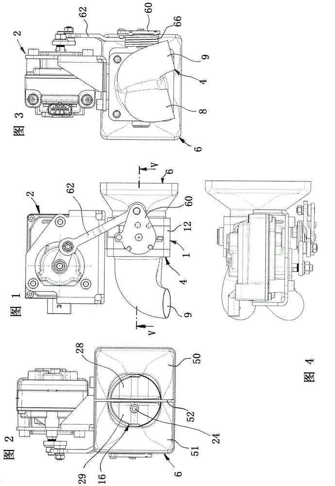
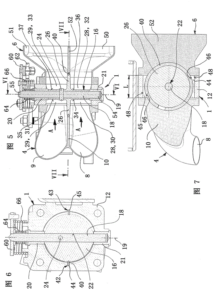
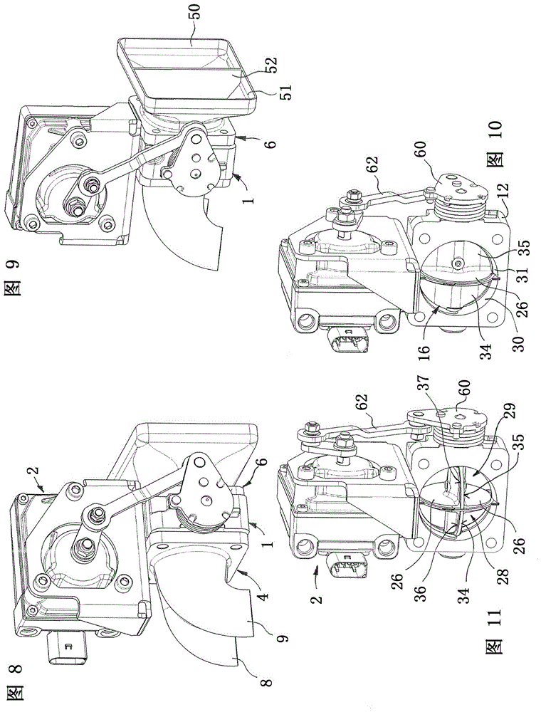
[0035] Figures 1 to 12 An assembly for an exhaust system of an internal combustion engine is shown, comprising a valve 1 , an actuator 2 , an inlet flange 4 and an outlet flange 6 . The inflow flange 4 includes two conduits 8, 9, which are separated by a spacer 10 in the inflow flange 4; see for details Figure 5 . A pipe can be welded to the inflow flange 4 at each conduit 8 , 9 in a manner not shown in detail. The internal combustion engine (not shown) may have, for example, six cylinders. Exhaust gases from a first group of cylinders (eg cylinders 1 to 3 ) can be fed to a first conduit 8 which flows into flange 4 . Exhaust gas from a second group comprising, for example, cylinders 4 to 6 can be fed to a second conduit 9 which flows into flange 4 .
[0036] The valve 1 is a flap-type exhaust gas recirculation valve and comprises a housing 12 with a channel 14 through which the exhaust gas can flow in flow direction A; see in detail Figure 12 . A closing body 16 is ar...
PUM
 Abstract
Description
Claims
Application Information
 - R&D
- Intellectual Property
- Life Sciences
- Materials
- Tech Scout
- Unparalleled Data Quality
- Higher Quality Content
- 60% Fewer Hallucinations
Browse by: Latest US Patents, China's latest patents, Technical Efficacy Thesaurus, Application Domain, Technology Topic, Popular Technical Reports.
© 2025 PatSnap. All rights reserved.Legal|Privacy policy|Modern Slavery Act Transparency Statement|Sitemap|About US| Contact US: help@patsnap.com


