
Yaw brake and wind driven generator using yaw brake

A technology for yaw brakes and wind generators, which is applied in wind turbines, control of wind turbines, and wind power generation. It can solve problems such as high cost and poor detection accuracy, achieve accurate wear, simple structure, and improve detection accuracy. Effect

Inactive Publication Date: 2016-10-12
XUJI GRP +2
View PDF8 Cites 1 Cited by
  • Summary
  • Abstract
  • Description
  • Claims
  • Application Information

AI Technical Summary

Problems solved by technology

[0007] The purpose of the present invention is to provide a yaw brake and a wind power generator using the yaw brake to solve the problems of poor detection accuracy and high cost of the existing yaw brake friction plate wear

Method used


Image

  • Yaw brake and wind driven generator using yaw brake
  • Yaw brake and wind driven generator using yaw brake
  • Yaw brake and wind driven generator using yaw brake

Examples


Embodiment Construction

[0023] Embodiments of the present invention will be further described below in conjunction with the accompanying drawings.

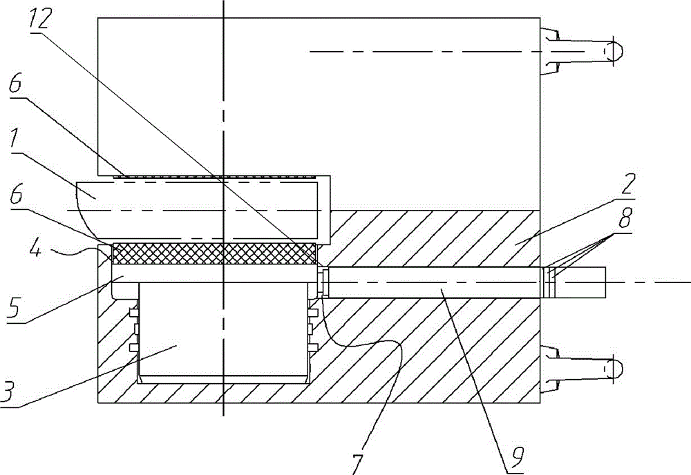
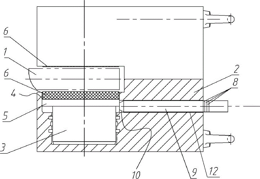
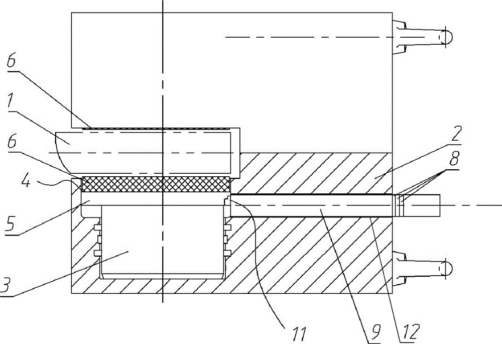
[0024] Embodiments of the yaw brake of the present invention are as figure 1 As shown, it includes a caliper body 2 , a friction plate 4 movable vertically on the caliper body 2 , and an oil cylinder 3 for driving the friction plate 4 to clamp or release the brake disc 1 . The friction plate 4 includes a friction plate base plate 5 and a friction material plate 6 arranged on the top surface of the friction plate base plate 5 .

[0025] Definition The transverse direction is the direction perpendicular to the clamping movement direction of the friction plate 4. A transverse through hole is provided on the outer surface of the caliper body 2 to form a detection tool insertion hole 12. The inner end of the detection tool insertion hole 12 faces the friction plate substrate 5 . The friction sheet substrate 5 is a flat plate structure, with a bottom surface...


PUM


Abstract

The invention relates to a yaw brake and a wind driven generator using the yaw brake. The yaw brake comprises a plier body and a friction piece. The friction piece comprises a friction piece base plate. A detection tool insertion hole is formed in the outer side face of the plier body. The transverse direction is defined to be the direction perpendicular to the clamping movement direction of the friction piece. The detection tool insertion hole extends in the transverse direction. The inner end of the detection tool insertion hole faces the friction piece base plate. The friction piece base plate is provided with a detection tool blocking face which is of the transverse size and changes in the clamping movement direction of the friction piece, or is provided with a detection tool supporting part matched with the reducing end of an inserted type detection tool in the transverse direction in a supporting manner. According to the yaw brake, the abrasion loss is conveniently observed, the detection precision can be ensured, and cost is low.

Description

technical field [0001] The invention relates to a yaw brake and a wind power generator using the yaw brake. Background technique [0002] Wind power is a kind of clean renewable energy, which has been paid more and more attention by countries all over the world. Since the wind direction of the wind field is constantly changing, in order to utilize wind energy efficiently, the rotor blades of the fan must always be aligned with the wind direction during operation. For this reason, a yaw system is installed on the top of the wind turbine inner tower. There are two main functions of the yaw system: one is to cooperate with the control system of the wind turbine, so that the wind rotor of the wind turbine is always in the windward state, making full use of wind energy and improving the power generation efficiency of the wind turbine; the other is Provide the necessary locking torque to ensure the safe operation of the wind turbine. [0003] The yaw system generally consists of...

Claims


Application Information

Patent Timeline
Patent Type & Authority Applications(China)
IPC IPC(8): F16D66/02F03D7/00
CPCF03D7/00F16D66/021F16D66/026Y02E10/72
Inventor 杨海锋卢仁宝王立飞张小伟白海松王建伟耿丽红谢金娟李松博武愈振
Owner XUJI GRP
Learn More