Lubricating structure for automobile motor and gearbox

A technology of lubricating structure and gearbox, applied in the direction of gear lubrication/cooling, electromechanical devices, electrical components, etc., can solve the problems of high cost, reduced service life of spline pairs, short return maintenance period, etc., and achieves a simple filling method. , easy to operate, prolong the effect of the cycle

Inactive Publication Date: 2016-10-12
UNIV OF ELECTRONICS SCI & TECH OF CHINA ZHONGSHAN INST
View PDF7 Cites 0 Cited by
  • Summary
  • Abstract
  • Description
  • Claims
  • Application Information

AI Technical Summary

Problems solved by technology

[0002] In the prior art, the motor and the gearbox are usually connected together by splines, and the spline pair will be worn during the operation of the motor and the gearbox. The common solution is to remove the motor and the gearbox from the car. Disassemble and separate in the middle, disassemble the connection between the motor and the gearbox, add lubricating oil to the spline pair, and seal the lubricating oil in the spline pair to ensure that the lubricating oil will not be thrown out when the car is running. Lubricating oil is added during car maintenance to reduce the wear of the spline pair and ensure the service life of the spline pair, but there are the following shortcomings; first, the return maintenance period is short, and the car needs to be maintained irregularly. To avoid wear of the spline pair caused by running out of lubricating oil, and reduce the service life of the spline pair; second, it is troublesome to fill the lubricating oil, and the spline connection between the motor and the gearbox needs to be disassembled. After the filling is completed, it needs to be refilled. Connecting and installing the motor and gearbox together and putting them back into the car, manual operation is inefficient and costly, reducing the market competitiveness of the car

Method used


Image

  • Lubricating structure for automobile motor and gearbox
  • Lubricating structure for automobile motor and gearbox
  • Lubricating structure for automobile motor and gearbox

Examples


Embodiment Construction

[0020] The structural principle and working principle of the present invention will be further described in detail below in conjunction with the accompanying drawings.

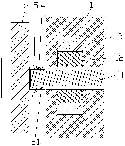
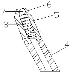
[0021] Such as Figure 1-Figure 6 As shown, a lubricating structure of an automobile motor and a gearbox includes a motor 1 and a gearbox 2, the motor 1 includes a first rotating shaft 11, a rotor assembly 12 and a stator assembly 13, and the rotor assembly 12 is installed on the outside of the first rotating shaft 11, The stator assembly 13 is nested on the outside of the rotor assembly 12, the gearbox 2 includes a second shaft 21, the first shaft 11 and the second shaft 21 are further connected, and the contact surface of the first shaft 11 and the second shaft 21 Lubricating track 3 is provided, and the number of lubricating track 3 is more than one. The second rotating shaft 21 is provided with an oil inlet passage 4, and the oil inlet passage 4 is arranged obliquely. The oil inlet passage 4 extends from o...


PUM


Abstract

The invention discloses a lubricating structure for an automobile motor and a gearbox. A rotor assembly is mounted outside a first rotating shaft. A stator assembly is nested at the outer side of the rotor assembly. The gearbox comprises a second rotating shaft. The first rotating shaft and the second rotating shaft are further connected. One or more lubricating tracks are arranged on the contact surface of the first rotating shaft and the second rotating shaft. An oil inlet channel is formed in the second rotating shaft and arranged to be inclined. The oil inlet channel extends into the inner side of the second rotating shaft from one end of the second rotating shaft and is provided with an anti-leakage nozzle. One end of the anti-leakage nozzle is fixedly connected with the oil inlet channel, and the other end of the anti-leakage nozzle is provided with a tip-shaped leaking head. A blocking ball is arranged inside the tip-shaped leaking head. A spring is arranged below the blocking ball. The blocking ball can move up and down in the anti-leakage nozzle through the spring. By means of the lubricating structure for the automobile motor and the gearbox, the lubricating oil filling cycle of the motor and the gearbox is effectively prolonged; the filling method is simple; and the lubricating structure is convenient to operate, high in speed and high in efficiency.

Description

technical field [0001] The invention belongs to the technical field of motors, and in particular relates to a lubricating structure for an automobile motor and a gearbox. Background technique [0002] In the prior art, the motor and the gearbox are usually connected together by splines, and the spline pair will be worn during the operation of the motor and the gearbox. The common solution is to remove the motor and the gearbox from the car. Disassemble and separate in the middle, disassemble the connection between the motor and the gearbox, add lubricating oil to the spline pair, and seal the lubricating oil in the spline pair to ensure that the lubricating oil will not be thrown out when the car is running. Lubricating oil is added during car maintenance to reduce the wear of the spline pair and ensure the service life of the spline pair, but there are the following shortcomings; first, the return maintenance period is short, and the car needs to be maintained irregularly. ...

Claims


Application Information

Patent Timeline
Patent Type & Authority Applications(China)
IPC IPC(8): F16H57/04F16C3/02H02K7/116
CPCF16H57/043F16C3/02F16C2361/31H02K7/116
Inventor 夏百战杨亮石世光
Owner UNIV OF ELECTRONICS SCI & TECH OF CHINA ZHONGSHAN INST
Why Eureka
Try Eureka