
Using method of movable sealing device

A technology of moving sealing and rubber sealing ring, applied in the direction of engine sealing, engine components, mechanical equipment, etc., can solve the problems of inflexible sealing and frequent relative movement, and achieve the effect of ensuring sealing effect and convenient disassembly.

Active Publication Date: 2016-10-12
MAANSHAN GELIN MINING & METALLURGY ENVIRONMENTAL PROTECTION EQUIP
View PDF7 Cites 0 Cited by
  • Summary
  • Abstract
  • Description
  • Claims
  • Application Information

AI Technical Summary

Problems solved by technology

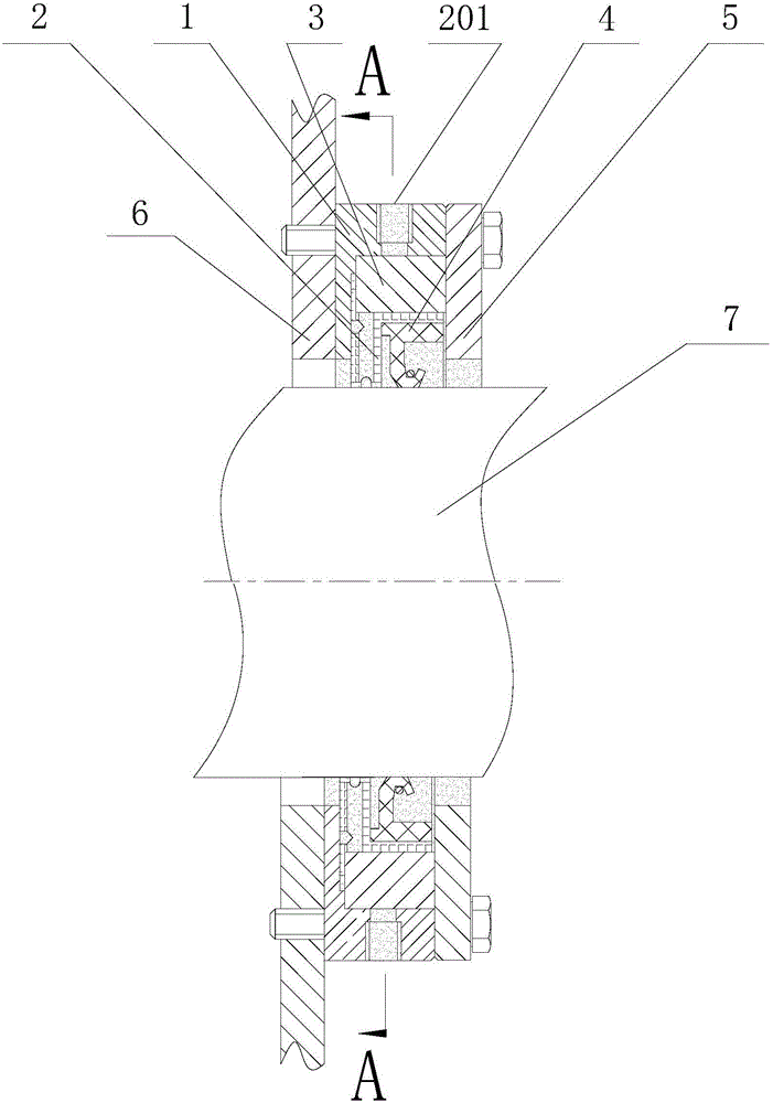
[0006] Aiming at the problems of inflexible sealing and unsuitable for frequent relative movement between fixed parts and moving parts in existing sealing rings, the present invention provides a method for using a movable sealing device, including an outer ring body, an inner ring body, a rubber seal The outer ring body and the bearing cover are fixed by bolts, which can meet the demand for a large gap between the pressure roller and the rotating shaft; the inner ring body is equipped with a rubber sealing ring, so that the side of the inner ring body close to the rotating shaft and the rotating shaft In close contact, the radially opposite sides of the inner ring body are plane structures, and the limit rod is set between the plane structure of the inner ring body and the outer ring body. When the shaft and the end cover are displaced, the inner ring body and the inner rubber The sealing ring can move horizontally relative to the outer ring body to realize the sealing function

Method used


Image

  • Using method of movable sealing device
  • Using method of movable sealing device
  • Using method of movable sealing device

Examples


Embodiment 1

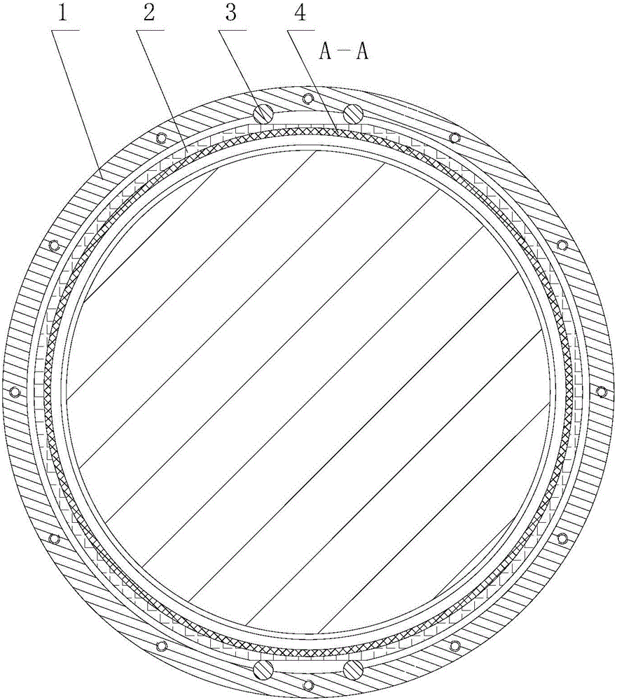
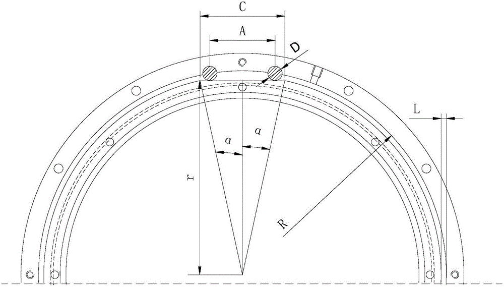
[0033] Such as figure 1 , figure 2 with image 3As shown, a movable sealing device includes an outer ring body 1, an inner ring body 2, a rubber sealing ring 4, a gland 5 and a limit rod 3, and the outer ring body 1 and the inner ring body 2 are both ring-shaped, The cross sections of the outer ring body 1 and the inner ring body 2 are both in the shape of "7", which are divided into vertical planes and horizontal planes; the outer diameter of the outer ring body 1 is 0.2m, the thickness is 35mm, and the inner diameter 2R of the outer ring body 1 is 183mm , the difference 2L between the inner diameter of the outer ring body 1 and the outer diameter of the inner ring body 2 is 5mm, the inner side of the horizontal plane of the outer ring body 1 is provided with an annular groove, and the thickness of the inner ring body 2 is smaller than the annular groove inside the outer ring body 1 The width of the inner ring body 2 is set in the annular groove; the rubber sealing ring 4 ...

Embodiment 2

[0036] Such as figure 1 , figure 2 with image 3 As shown, a movable sealing device includes an outer ring body 1, an inner ring body 2, a rubber sealing ring 4, a gland 5 and a limit rod 3, and the outer ring body 1 and the inner ring body 2 are both ring-shaped, The cross sections of the outer ring body 1 and the inner ring body 2 are both in the shape of "7", which are divided into vertical planes and horizontal planes; the outer diameter of the outer ring body 1 is 1.0m, the thickness is 45mm, and the inner diameter 2R of the outer ring body 1 is 914mm , the difference 2L between the inner diameter of the outer ring body 1 and the outer diameter of the inner ring body 2 is 24mm, the inner side of the horizontal plane of the outer ring body 1 is provided with an annular groove, and the thickness of the inner ring body 2 is smaller than the annular groove inside the outer ring body 1 The width of the inner ring body 2 is set in the annular groove; the rubber sealing ring ...

Embodiment 3

[0039] Such as figure 1 , figure 2 with image 3 As shown, a movable sealing device includes an outer ring body 1, an inner ring body 2, a rubber sealing ring 4, a gland 5 and a limit rod 3, and the outer ring body 1 and the inner ring body 2 are both ring-shaped, The cross sections of the outer ring body 1 and the inner ring body 2 are both in the shape of "7", which are divided into vertical planes and horizontal planes; the outer diameter of the outer ring body 1 is 2.0m, the thickness is 60mm, and the inner diameter 2R of the outer ring body 1 is 1828mm , the difference 2L between the inner diameter of the outer ring body 1 and the outer diameter of the inner ring body 2 is 48mm, the inner side of the horizontal plane of the outer ring body 1 is provided with an annular groove, and the thickness of the inner ring body 2 is smaller than the annular groove inside the outer ring body 1 The width of the inner ring body 2 is set in the annular groove; the rubber sealing ring...


PUM


Abstract

The invention discloses a using method of a movable sealing device and belongs to the field of mechanical device sealing pieces. The movable sealing device comprises an outer ring body, an inner ring body and a rubber sealing ring and further comprises a limiting rod; the outer ring body and a bearing cover are fixed through a bolt, and the requirement that a gap between a pressing roller and a rotating shaft is large can be met; the rubber sealing ring is arranged in the inner ring body so that the side, close to the rotating shaft, of the inner ring body can be in close contact with the rotating shaft; the two outer sides, opposite to each other in the radial direction, of the inner ring body are of a plane structure; the limiting rod is arranged between the plane structure of the inner ring body and the outer ring body; and when the rotating shaft and an end cover move, the inner ring body and the inner rubber sealing ring can horizontally move relative to the outer ring body so that the sealing function can be achieved. The movable sealing device has the beneficial effects of being simple in structure, reasonable in design, easy to manufacture and good in sealing effect and is especially suitable for sealing between a movable piece and a fixed piece.

Description

[0001] This invention is a divisional application, the original Chinese patent application number: 201510203464.7, the application date: April 24, 2015, the patent name at the time of application: a movable sealing device and its use method. technical field [0002] The invention belongs to the field of mechanical device seals, and more specifically relates to a method for using a movable sealing device. Background technique [0003] High-pressure roller mill is a new type of energy-saving grinding equipment that came out in the mid-1980s. It is one of the intermediate equipment in the process of cement grinding and metal ore crushing. It is the key equipment to achieve more crushing and less grinding. Significantly reduce energy consumption. After the high-pressure roller mill has been greatly popularized and applied in the cement field, in order to make it popular in the metal mine field, the roller surface of the cemented carbide stud is used, which greatly improves the w...

Claims


Application Information

Patent Timeline
Patent Type & Authority Applications(China)
IPC IPC(8): F16J15/3208F16J15/324F16J15/3268F16J15/40F16J15/3284
CPCF16J15/3208F16J15/324F16J15/3268F16J15/40F16J15/406
Inventor 于江李书会曹铁峰汪再青梁锋姜立新
Owner MAANSHAN GELIN MINING & METALLURGY ENVIRONMENTAL PROTECTION EQUIP
Learn More