Rectification noise reduction air duct

A technology for air outlet and noise reduction, which is applied in the direction of pipes, pipe components, rigid pipes, etc., and can solve the problem of air flow obstruction in the air outlet

Active Publication Date: 2021-04-09
SKYBEST ELECTRIC APPLIANCE SUZHOU CO LTD
View PDF1 Cites 1 Cited by
  • Summary
  • Abstract
  • Description
  • Claims
  • Application Information

AI Technical Summary

Problems solved by technology

[0004] The purpose of the present invention is to solve the defects existing in the prior art, and to provide a rectifying and noise-reducing air outlet pipe, which aims to solve the problems caused by the existing air outlet pipe grid circle when the air outlet pipe is short or the air outlet end is turbulent. The problem of airflow obstruction in the air outlet pipe

Method used


Image

  • Rectification noise reduction air duct
  • Rectification noise reduction air duct
  • Rectification noise reduction air duct

Examples


Embodiment 1

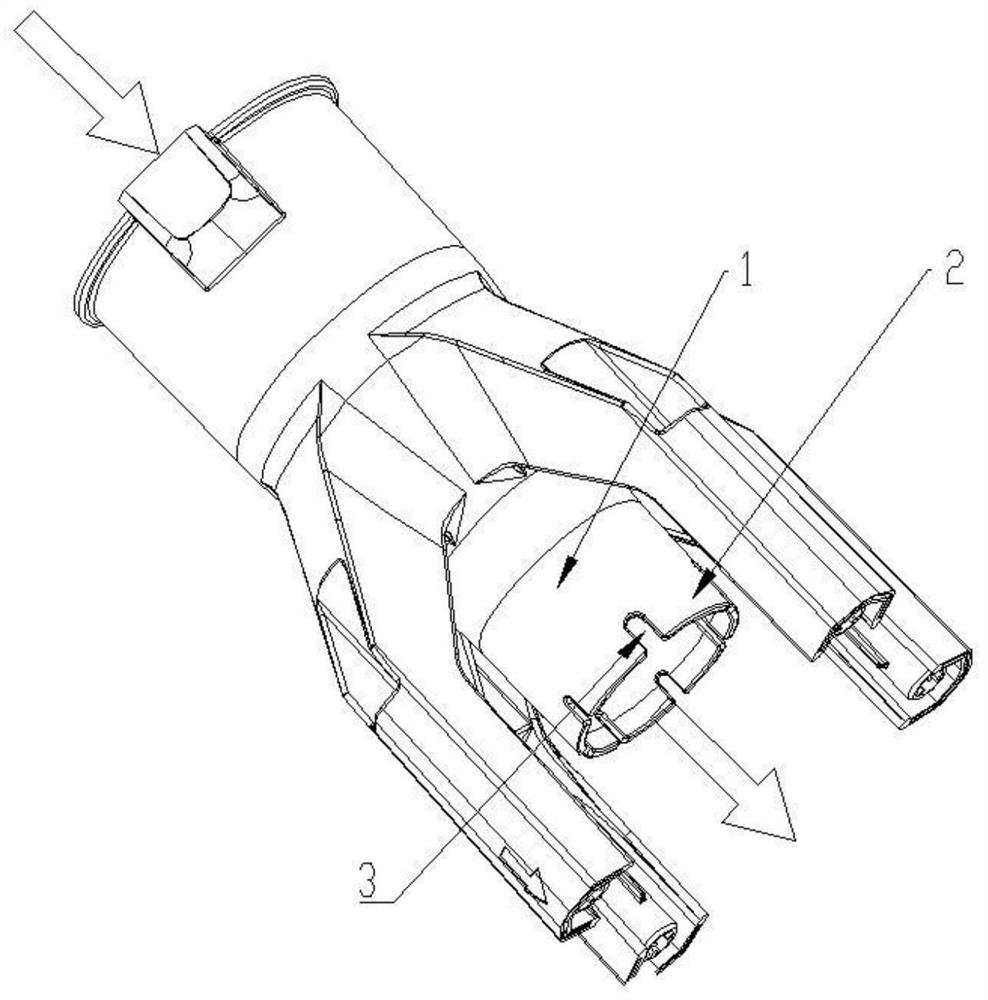
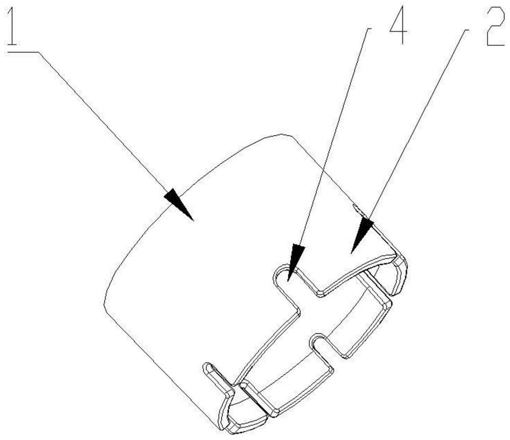
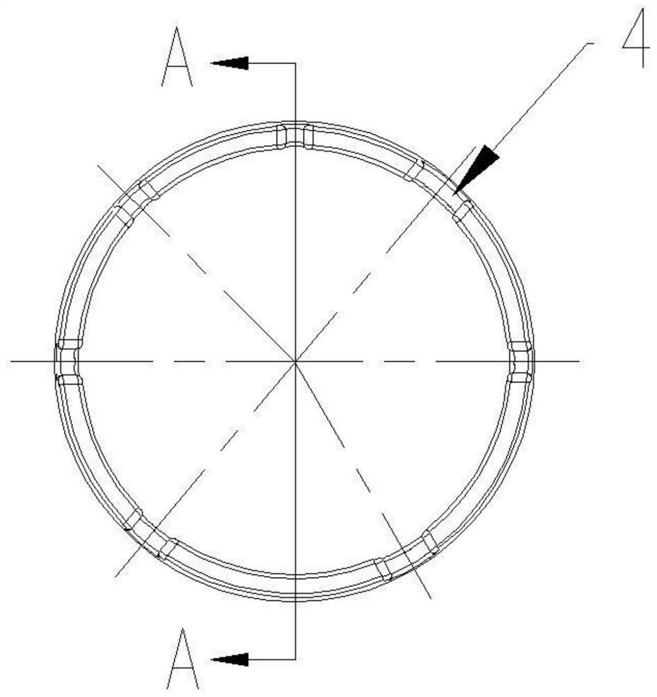
[0039] Such as Figure 2 to Figure 4 As shown, the concavo-convex body is a plurality of grooves 4, and at least one dimension of at least two grooves 4 in the guide part 3 is different from the previous year, and / or, the grooves of the guide part are unevenly distributed on the inner wall of the port pipe wall 2, and the grooves The dimensions of 4 include the radial groove depth, the axial groove length, and the circumferential groove width with reference to the main body of the air outlet pipe; the year-on-year difference in dimensions includes the following differences: the difference in radial groove depth; Figure 4 Shown are axial groove lengths that vary; as in image 3 Different circumferential groove widths are shown; as image 3 As shown, the grooves are unevenly distributed on the inner wall of the port pipe wall 2; more preferably, the circumferential distances between any two grooves in the guide part 3 are different.

[0040] It should be noted that the groove...

Embodiment 2

[0046] Such as Figure 5 to Figure 7 As shown, the concavo-convex body is a plurality of ribs 5, and at least one dimension of at least two ribs 5 in the guide portion is different from the previous year and / or the ribs of the guide portion are unevenly distributed on the inner wall of the port pipe wall 2, and the ribs The dimensions of ribs include radial rib depth, axial rib length, and circumferential rib width. The ribs 5 are protrusions arranged radially along the air outlet pipe, and the protrusions are used to divert and redirect the wind flow. The year-on-year difference in dimension size includes the following differences: difference in radial rib depth; Figure 7 Different axial rib lengths are shown; as Image 6 Different circumferential rib widths are shown; as Image 6 As shown, the ribs are unevenly distributed on the inner wall of the port pipe wall 2; more preferably, the circumferential distances between any two ribs in the guide portion 3 are different.

...

Embodiment 3

[0052] Such as Figure 8 to Figure 10 As shown, the concavo-convex bodies are at least two grooves 4 and at least two ribs 5, wherein the dimensions and distribution characteristics of the grooves refer to Embodiment 1, and the dimensions and distribution characteristics of the ribs refer to Embodiment 2, the difference is that the concavo-convex The body is unevenly distributed on the inner wall of the port pipe wall 2, that is, the uneven distribution defines grooves and ribs at the same time.

[0053] Similar to the foregoing, the number of grooves 4 and ribs 5 is any number not less than two. In particular, when the number of grooves 4 and ribs 5 is a prime number, such as 3, 5, 7, 11, 13, etc., the generation of resonance can be effectively avoided and the noise cancellation effect can be enhanced.


PUM


Abstract

The invention discloses a rectifying and noise-reducing air outlet pipe, which is assembled on the air outlet end of electrical equipment such as a blower and suction machine. The guide part includes a plurality of concave-convex bodies as grooves and / or ribs. The air outlet pipe of the present invention has a rectifying and noise-reducing structure, and a guide part is provided in the port wall of the air outlet pipe, through which the air flow can be differentially diverted, so that the wind energy rectifies the turbulent flow and eliminates the impact of the turbulent flow on the wind. The air outlet resistance of the air outlet pipe makes the air flow smooth and reduces the working noise; the guide part of the air outlet pipe has little resistance to the air flow, and can effectively reduce the velocity gradient at the air outlet and reduce the noise; the rectification of the air outlet pipe reduces the noise. The noise structure is simple and ingenious, which is convenient for production and processing.

Description

technical field [0001] The invention relates to an air outlet pipe of electrical equipment, in particular to an air outlet pipe with a rectification and noise reduction structure, belonging to the technical field of F16L9 / 21 in the International Patent Classification Table. Background technique [0002] The air outlet pipe is the part that leads out the airflow generated by the electrical equipment. Taking the blower and suction machine as an example, in the past, no ribs were added to the air outlet pipe of the blower and suction machine, or some regular grids were added to meet the requirements of "safety regulations" Ribs, this structure, when the air outlet pipe is short or the air flow at the outlet end is turbulent, the grid ribs will hinder the air flow in the air outlet pipe, resulting in a decrease in the air output of the air outlet pipe and easy With the problem of increased noise, it also increases the load on electrical equipment and increases energy consumption...

Claims


Application Information

Patent Timeline
Patent Type & Authority Patents(China)
IPC IPC(8): F16L9/21F16L55/033
CPCF16L9/21F16L55/033
Inventor 孔钊张天才雷艳清
Owner SKYBEST ELECTRIC APPLIANCE SUZHOU CO LTD
Why Eureka
Try Eureka