Whole-glass heat pipe vacuum solar collector

An all-glass, heat collector technology, applied in the direction of solar heat collectors, solar heat collectors using working fluids, fluid circuit connections of solar heat collectors, etc.

Inactive Publication Date: 2016-10-12
SHANDONG HUAYU UNIV OF TECH
View PDF8 Cites 3 Cited by
  • Summary
  • Abstract
  • Description
  • Claims
  • Application Information

AI Technical Summary

Problems solved by technology

[0007] The object of the present invention is to provide a kind of all-glass heat pipe

Method used


Image

  • Whole-glass heat pipe vacuum solar collector
  • Whole-glass heat pipe vacuum solar collector
  • Whole-glass heat pipe vacuum solar collector

Examples


Embodiment 1

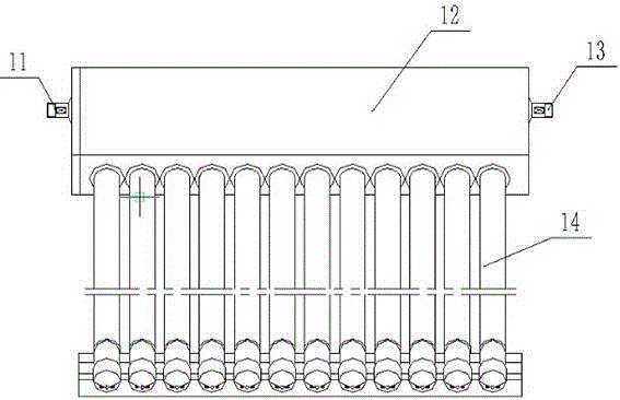
[0033] Embodiment 1: as figure 1 Shown is a schematic structural view of Embodiment 1 of the all-glass heat pipe vacuum solar collector of the present invention, which includes two parts: a header 12 and an all-glass heat pipe vacuum solar collector tube 14. The mouth of the all-glass heat pipe vacuum solar collector tube 14 is directly inserted into the header 12, and the sunlight is absorbed by the all-glass heat pipe vacuum solar collector tube 14 and converted into heat, which is transmitted to the water in the header 12, and installed on both sides of the header 12 There is a water inlet 11 and a water outlet 13, water enters the header 12 from the water inlet 11, and flows out from the water outlet 13 after being heated.

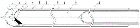
[0034] figure 2 It is a structural schematic view of the all-glass heat pipe vacuum solar collector tube 14 in Embodiment 1 of the present invention. figure 2 Among them, the cover glass tube 8 and the inner glass tube 7 are both closed at one end,...

Embodiment 2

[0040] Embodiment 2: as Figure 4 , Figure 5 and Image 6 Shown, embodiment 2 is identical with embodiment 1 basic structure, and its difference is:

[0041] Figure 4 It is a schematic structural view of an all-glass heat pipe vacuum solar collector tube in Embodiment 2 of the present invention, which has the same basic structure as Embodiment 1, and its difference lies in Embodiment 1, see figure 2 , the solar selective absorbing coating 6 is only attached to the outer surface of the inner glass tube 7; in embodiment 2, as Figure 4 As shown, the solar selective absorbing coating 6 is attached to the outer surface of the inner glass tube 7 and part of the outer surface of the evaporation section 10 .

[0042] Figure 5 It is a schematic cross-sectional structure diagram of the all-glass heat pipe vacuum solar collector of Embodiment 2 of the present invention, which is the same as Embodiment 1 in basic structure, and its difference lies in Embodiment 1, see image 3 , ...

Embodiment 3

[0044] Embodiment 3: as Figure 7 , Figure 8 and Figure 9 Shown, embodiment 3 is identical with embodiment 1 and embodiment 2 basic structures, and its difference is:

[0045] Figure 7 It is a structural schematic diagram of an all-glass heat pipe vacuum solar heat collecting tube in Embodiment 3 of the present invention. The basic structure is the same as the schematic diagram of the structure of the all-glass heat pipe vacuum solar collector tube in embodiment 1 and implementation 2, and its difference is that: the cover glass tube 8, the inner glass tube 7, and the condenser tube 10 are directly annularly fused together, and the condenser tube Glass tube 25 in water is arranged in 10, can reduce the water content in condensation pipe 10.

[0046] Figure 8 It is a schematic cross-sectional structure diagram of the all-glass heat pipe vacuum solar collector of embodiment 3, which is basically the same as the cross-sectional structural schematic diagram of the header in...


PUM


Abstract

A whole-glass heat pipe vacuum solar collector comprises a header and a whole-glass heat pipe vacuum solar collecting pipe with one end inserted in the header and connected with the header in a sealed manner; an inner container is arranged in the header; the whole-glass heat pipe vacuum solar collecting pipe comprises a hood glass pipe, an inner glass pipe connected in the hood glass pipe in a sleeved manner, and a condensation pipe connected in the inner glass pipe in a sleeved manner; the hood glass pipe, the inner glass pipe and the condensation pipe are each provided with a semispherical closed end and an open end; a vacuum interlayer is arranged between the hood glass pipe and the inner glass pipe; the outer wall of the inner glass pipe is plated with a solar selective absorption coating; the inner glass pipe and the condensation pipe are closed to form an evaporation segment which is filled with a heat transfer working medium; and the heat transfer work medium penetrates the pipe wall of the condensation pipe to heat water in the inner container. The whole-glass heat pipe vacuum solar collector solves the problem that because water passes through the interior of a common whole-glass vacuum pipe, damage is easily caused in winter.

Description

technical field [0001] The invention relates to the field of solar heat utilization, in particular to an all-glass heat pipe vacuum solar collector. Background technique [0002] The all-glass vacuum solar collector tube is the core component of the collector. The existing all-glass vacuum solar collector tube is like an elongated thermos bile as a whole, and is specifically composed of two inner glass tubes and cover glass tubes that are set together. The outer surface of the glass tube is deposited with a solar selective absorbing surface, coating or film system to form a heat absorber, so as to convert solar energy into heat energy, thereby heating the heat transfer fluid in the inner glass tube. The inner glass tube and the cover glass tube in the all-glass vacuum solar collector tube are concentrically arranged, and a single-ended opening design is adopted. The inner glass tube and the cover glass tube at one end are sealed by ring fusion, and the other end is a closed...

Claims


Application Information

Patent Timeline
IPC IPC(8): F24J2/05F24J2/32F24J2/46F24S10/40F24S10/95
CPCF24S10/45F24S10/90F24S80/30Y02E10/44
Inventor 孔德霞张风合魏丰君
Owner SHANDONG HUAYU UNIV OF TECH
Why Eureka
Try Eureka