Temperature sensor integrated in RFID tag

A technology of RFID tags and temperature sensors, applied in the field of RFID, can solve problems such as chip area power reduction, area and energy consumption, unfavorable costs, etc., and achieve the effects of chip area reduction, power consumption reduction, and cost reduction

Pending Publication Date: 2016-10-12
GUANGZHOU SYSUR MICROELECTRONICS
View PDF8 Cites 10 Cited by
  • Summary
  • Abstract
  • Description
  • Claims
  • Application Information

AI Technical Summary

Problems solved by technology

like figure 1 As shown, the CMOS integrated temperature sensor is mainly divided into three categories according to the system structure: (1) BJT (bipolar transistor) temperature sensor combined with ADC structure. The advantages of this sensor are high precision and wide measurement range. The disadvantage is that the chip The area is large, the power consumption is very high and the data conversion rate is low, so it is not suitable for integration in passive tags; (2) The temperature sensor with an oscillator combined with a frequency-to-digital conversion structure requires an additional design of an oscillator, which cannot effectively utilize the inherent Oscillators cause unnecessary area and energy consumption, and are not suitable for integration in passive tags; (3) A temperature sensor with a pulse-combined time-to-digital conversion structure. The biggest advantage of this sensor is that it has low power consumption and occupies a small chip area. Suitable for integration in passive tags
[0004] Although the temperature sensor with pulse-combined time-to-digital conversion structure is more suitable for integration in RFID passive tags, because the common module circuit between the temperature sensor and other modules is still relatively small, it limits the further reduction of chip area and power consumption. , and it is not conducive to the further reduction of cost

Method used


Image

  • Temperature sensor integrated in RFID tag
  • Temperature sensor integrated in RFID tag
  • Temperature sensor integrated in RFID tag

Examples


no. 1 example

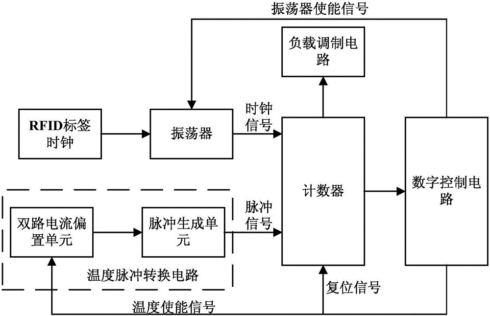
[0026] Aiming at the problem that there are relatively few shared module circuits between the temperature sensor and other modules in the prior art, the present invention proposes a brand-new temperature sensor integrated in the RFID tag. The system structure of the temperature sensor is as follows: figure 2 As shown, it is mainly composed of temperature pulse conversion circuit, counter, digital control circuit, oscillator, RFID tag clock and load modulation circuit. The working principle of the present invention is as follows:

[0027] When the system is working, firstly, the digital control circuit sends a control signal to the oscillator to make it output the system clock according to the RFID tag clock. After the system clock works, the digital control circuit sends a reset signal to clear the counter, and at the same time sends a temperature enable signal to the temperature pulse conversion circuit to control it to start collecting temperature information. After the in...


PUM


Abstract

The invention discloses a temperature sensor integrated in an RFID tag. The temperature sensor comprises a temperature pulse conversion circuit, a counter, an oscillator, an RFID tag clock, a digital control circuit and a load modulation circuit; the counter, the oscillator, the RFID tag clock, the digital control circuit and the load modulation circuit are all common module circuits between the temperature sensor and other modules; the output end of the RFID tag clock is connected with the input end of the digital control circuit through the oscillator and the counter sequentially; the output end of the temperature pulse conversion circuit is connected with the enabling end of the counter; the output ends of the digital control circuit are connected with the reset end of the counter, the temperature enabling end of the temperature pulse conversion circuit and the enabling end of the oscillator; and one output end of the counter is connected with the input end of the load modulation circuit. The temperature sensor of the invention has the advantages of small chip area, low power consumption and low cost, and can be widely applied to the RFID technology field.

Description

technical field [0001] The invention relates to the technical field of RFID, in particular to a temperature sensor integrated in an RFID tag. Background technique [0002] RFID technology has many advantages. After years of development, it has become increasingly mature, and the production of CMOS process integrated chips has reduced its production costs and broadened its application fields. The introduction of technology strategies such as the Internet of Things has brought broad application prospects for sensors as the basis of hardware, and at the same time put forward new requirements for applications with small size, low cost, and low power consumption. The temperature sensor based on the standard CMOS process and integrated on the RFID tag has the mature low-power technology basis of RFID and the technical advantages of low cost and small area of ​​the CMOS process. It can meet the new application requirements and has good practical value. [0003] When the RFID tag a...

Claims


Application Information

Patent Timeline
Patent Type & Authority Applications(China)
IPC IPC(8): G01K13/00G06K19/077
CPCG06K19/077G01K13/00
Inventor 胡建国吴劲王德明段志奎李启文周婧
Owner GUANGZHOU SYSUR MICROELECTRONICS
Why Eureka
Try Eureka