
Reflective slot wave frequency dispersion similarity-based tomographic imaging method

A technology of tomographic imaging and reflecting slot waves, which is applied to measurement devices, instruments, scientific instruments, etc., and can solve the problem of not using dispersion.

Active Publication Date: 2016-10-12
XIAN RES INST OF CHINA COAL TECH& ENG GROUP CORP
View PDF5 Cites 8 Cited by
  • Summary
  • Abstract
  • Description
  • Claims
  • Application Information

AI Technical Summary

Problems solved by technology

The existing methods, whether phase compensation or envelope calculation, do not take advantage of dispersion, and even regard it as harmful information and eliminate it

Method used


Image

  • Reflective slot wave frequency dispersion similarity-based tomographic imaging method
  • Reflective slot wave frequency dispersion similarity-based tomographic imaging method
  • Reflective slot wave frequency dispersion similarity-based tomographic imaging method

Examples


Embodiment Construction

[0066] In order to make the object, technical solution and advantages of the present invention clearer, the present invention will be further described in detail below in conjunction with the accompanying drawings and embodiments. It should be understood that the specific embodiments described here are only used to explain the present invention, not to limit the present invention.

[0067] An embodiment of the present invention provides a tomographic imaging method based on the similarity of reflection channel wave dispersion, which is realized by the following steps:

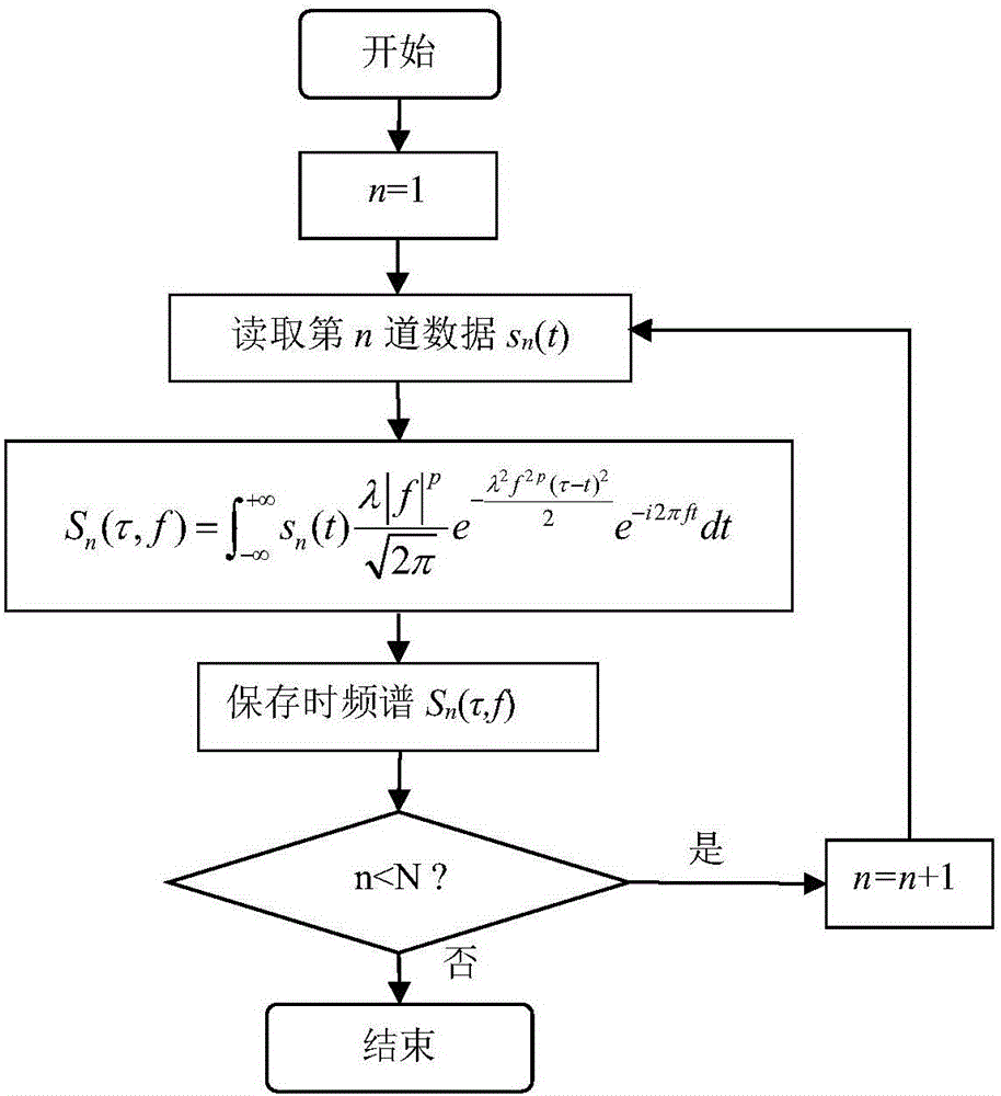
[0068] Step 1: Use the generalized S-transform to obtain the time-frequency spectrum of each channel of seismic data

[0069] S n ( τ , f ) = ∫ - ∞ + ∞ s n ...


PUM


Abstract

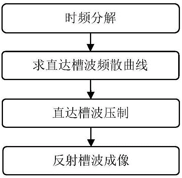
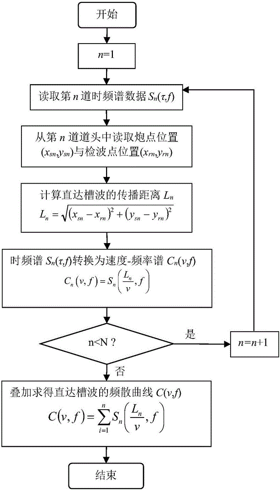
The invention discloses a reflective slot wave frequency dispersion similarity-based tomographic imaging method. The method is realized through the following steps: 1, conducting the time-frequency decomposition; 2, figuring out a through slot wave frequency dispersion curve; 3, eliminating through slot waves; 4, imaging. The method makes full use of the frequency dispersion properties of slot waves, and reduces the influence of other noises on the imaging process based on the frequency dispersion property. Meanwhile, the arc phenomenon is reduced, and the tomographic imaging accuracy is greatly improved.

Description

technical field [0001] The invention belongs to the technical field of coal mine underground geophysical prospecting, and in particular relates to a tomographic imaging method based on the dispersion similarity of reflection channel waves. Background technique [0002] The theoretical reflective channel wave imaging method is the time-delay summation migration method. The idea is to perform phase compensation for each channel signal based on the theoretical dispersion curve, but after calculating the delay time, the amplitude of each channel signal at the time of delay is superimposed. In actual data processing, the effect of phase compensation is not ideal due to the difference between the theoretical value and the actual value of the dispersion curve. Therefore, the common method is to obtain the envelope after performing band-pass filtering according to the center frequency, and then perform delay superposition on the envelope. When the reflected groove wave is strong e...

Claims


Application Information

Patent Timeline
IPC IPC(8): G01V1/30
CPCG01V1/306G01V2210/65
Inventor 王季何文欣李刚王保利陆斌姬广忠叶红星
Owner XIAN RES INST OF CHINA COAL TECH& ENG GROUP CORP
Learn More