Few-mode fiber device

A few-mode optical fiber and device technology, applied in the field of optical fiber communication, can solve problems such as poor output spectrum uniformity, difficulty in multiplexing and decomposition, and narrow operating bandwidth, and achieve good output energy uniformity, wide operating wavelength range, and polarization-independent Effect

Inactive Publication Date: 2016-10-12
JIANGSU UNIV
View PDF5 Cites 8 Cited by
  • Summary
  • Abstract
  • Description
  • Claims
  • Application Information

AI Technical Summary

Problems solved by technology

[0004] Generally, the conversion characteristics of mode converters based on the mode coupling principle have a strong wavelength dependence, narrow operating bandwidth, and poor output spectrum uniformity
Since the mode effective refractive index of the quadruple degenerate mode in the fiber is equal, there are also great difficulties in the multiplexing and decomposition of this mode
For the application of few-mode fiber systems, there is still a lack of effective means to selectively filter out one or some specific modes

Method used


Image

  • Few-mode fiber device
  • Few-mode fiber device
  • Few-mode fiber device

Examples


Embodiment 1

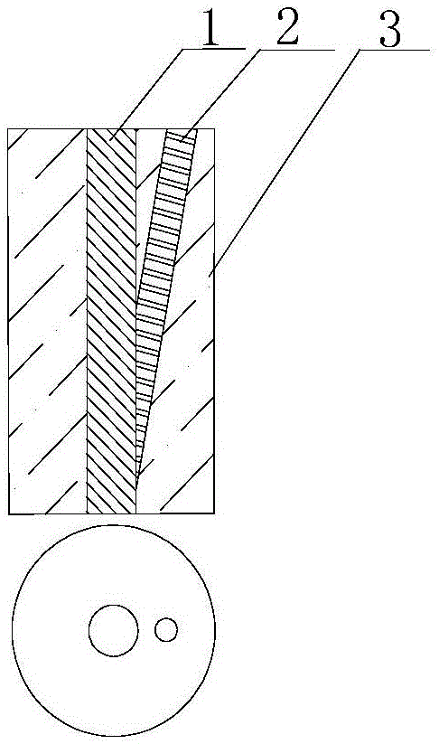
[0032] figure 1 It is a schematic diagram of the structure of the optical fiber embodiment 1 of the present invention. The number of auxiliary cores is M=1, and it satisfies: n i-1 >n f >n i (I≥i>1) or n f >n i (i=1); where, n i The effective refractive index of the i-th mode of the main core, I is the total number of modes of the main core, and there are n i-1 >n i (I≥i>1), n f is the effective refractive index of the fundamental mode of the auxiliary core. Both the main fiber core and the auxiliary fiber core have one number. There are main fiber core and auxiliary fiber core at the multi-core end face, while only the main fiber core exists at the single core end face.

[0033] At the working wavelength, the main fiber core 1 is a few-mode fiber core, that is, it can transmit high-order modes. The present invention implements operations such as introducing, extracting, and converting modes in the main fiber core 1 by introducing an auxiliary fiber core 2 .

[0034...

Embodiment 2

[0058] The invention can realize multiplexing and demultiplexing of optical fiber modes. The relationship between the quantity M of the auxiliary fiber core and the number of main fiber core modes I and the number of degenerate modules N of the main fiber core is: M=I+N; the central axes of I auxiliary fiber cores are in the same plane, and the auxiliary fiber core is defined as The first type of auxiliary fiber core is used to input the I modes of the main fiber core respectively; the central axis of the other N auxiliary fiber cores is not in this plane, which is defined as the second type of auxiliary fiber core, which is used to input the main fiber core respectively. Another of the N quadruple degenerate patterns.

[0059] Image 6 Given one of the schemes, there are 6 auxiliary fiber cores, of which 4 are first-type auxiliary fiber cores, and the central axes of the four first-type auxiliary fiber cores 21, 22, 23, 24 are connected to the center of the main fiber core. ...


PUM


Abstract

The invention provides a few-mode fiber device. The fiber core of the few-mode fiber device is formed by a main fiber core and auxiliary fiber cores, wherein the normalized frequency Vm of the main fiber core is larger than 2.405, and the number of the auxiliary fiber cores is M which is larger than or equal to 1. One end of each of the auxiliary fiber cores intersects with the side face of the main fiber core, and the central axis of the main fiber core and the central axes of the auxiliary fiber cores are on the same plane. The other end of each of the auxiliary fiber cores is on an optical fiber end face, and in the end face, the central distance between any two fiber cores is larger than the sum of the radii of the two fiber cores. The parameter between any auxiliary fiber core and the main fiber core satisfies a condition that the refractive index of at least one transmission mode of the main fiber core is lower than the effective refractive indexes of the auxiliary fiber cores. The invention provides the novel few-mode fiber device, and the conversion, combination, separation or elimination of the modes in a few-mode fiber can be realized.

Description

technical field [0001] The invention relates to the field of optical fiber communication, in particular to an optical fiber device capable of converting, merging, separating or filtering modes in a few-mode optical fiber. Background technique [0002] In recent years, due to the limitation of transmission capacity of single-mode fiber, the communication technology based on few-mode fiber has aroused widespread interest. The method of using few-mode fiber to transmit different information in different modes, the so-called mode division multiplexing technology, can double the transmission capacity of the fiber. At the same time, the few-mode fiber can also have a larger core area. In order to reduce the fiber nonlinear effect caused by various multiplexing technologies. In addition to the application of mode division multiplexing technology, few-mode fiber can also achieve large-mode field single-mode transmission, dispersion compensation, ultrashort pulse transmission and no...

Claims


Application Information

Patent Timeline
Patent Type & Authority Applications(China)
IPC IPC(8): G02B6/14G02B6/293
CPCG02B6/14G02B6/293G02B6/2938
Inventor 陈明阳曹国栋刘丕丕
Owner JIANGSU UNIV
Why Eureka
Try Eureka