Submodule unit of voltage source transverter based on full control components

A technology of voltage source converters and sub-modules, applied in output power conversion devices, conversion of AC power input to DC power output, electrical components, etc., can solve the problem of reducing work efficiency and operability, equipment dv/dt stress Large, inconvenient equipment maintenance and other problems, to achieve the effect of convenient installation and transportation, low output voltage change rate, convenient installation and maintenance

Active Publication Date: 2013-04-10
GLOBAL ENERGY INTERCONNECTION RES INST CO LTD +2
View PDF8 Cites 20 Cited by
  • Summary
  • Abstract
  • Description
  • Claims
  • Application Information

AI Technical Summary

Problems solved by technology

[0004] (1) The two-level voltage source converter adopts pulse width modulation technology, and the output voltage of the converter jumps between ±Udc/2 at high frequency, which brings about large dv/dt stress of equipment, large system loss, A series of problems such as high noise and harsh electromagnetic environment
Even the three-level voltage source converter can only alleviate the above problems to a certain extent
[0005] (2) The two-level and three-level voltage source commutation

Method used


Image

  • Submodule unit of voltage source transverter based on full control components
  • Submodule unit of voltage source transverter based on full control components
  • Submodule unit of voltage source transverter based on full control components

Examples


Example Embodiment

[0041] The specific embodiments of the present invention will be further described in detail below in conjunction with the accompanying drawings.

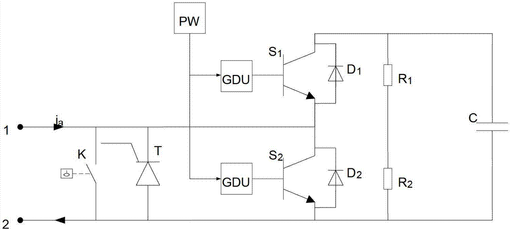
[0042] The sub-module unit of the voltage source converter in this embodiment adopts an independent control mode, and the electrical principle diagram of the sub-module unit is as follows: figure 1 As shown, this is a half-bridge structure of the IGBT module and the capacitor in parallel structure, this embodiment is determined to be the half-bridge structure or the upper half of the H-bridge structure is the upper tube IGBT module, for example figure 1 The IGBT module composed of the IGBT (S1) and the built-in diode D1 in parallel is the upper tube IGBT module (can be referred to as the upper IGBT), and the lower part of the half-bridge structure or the H-bridge structure is the lower tube IGBT module, for example figure 1 The IGBT module composed of the IGBT (S2) and the built-in diode D2 in parallel is the lower tube IGBT module (can ...


PUM


Abstract

The invention provides a submodule unit of a voltage source transverter based on full control components. The voltage source transverter is a three-phase six-bridge structure. Each bridge arm comprises a plurality of submodules which are connected in series. Each submodule comprises electric power components such as a capacitor, insulated gate bipolar translators (IGBT) modules with a structure of a semi-bridge, wherein the capacitor and the IGBT modules are connected in parallel. The submodule unit of the voltage source transverter based on the full control components further comprises a main support structure, a support plate, a connecting water pipe, radiators and the like. The main support structure is used for supporting the electric power components of the submodule unit, the support plate, the connecting water pipe and the radiators. The support plate is perpendicular to a base of the main support structure. The support plate is provided with the two radiators which are symmetrically arranged. The radiators are connected through the connecting water pipe. Two IGBT modules of each submodule are respectively arranged on the two radiators. The bottom of the capacitor of the each submodule is fixed on the base of the main support structure through bolts. The submodule unit of the voltage source transverter based on the full control components is a self-contained electrical system, is capable of expanding according to the need of the system, and is independent in structure and convenient to install and transport.

Description

technical field [0001] The invention belongs to the technical field of flexible direct current transmission, and in particular relates to a sub-module unit of a voltage source converter based on a full-control device. Background technique [0002] The high-voltage direct current transmission technology (VSC-HVDC) based on the voltage source converter was first proposed in 1900. Its main feature is that the voltage source converter composed of fully controlled power electronic devices replaces the half-controlled direct current transmission based on the conventional direct current transmission. Devices for current source converters. Since the technology was proposed, it has attracted the attention of many scholars and researchers all over the world due to its excellent controllability and flexibility. [0003] So far, there are several high-voltage direct current transmission projects based on voltage source converters in the world. There are some problems with the structur...

Claims


Application Information

Patent Timeline
IPC IPC(8): H02M7/00
CPCH02M7/003H05K7/20927H02M7/4835
Inventor 汤广福贺之渊栾洪洲吕铮欧阳文敏
Owner GLOBAL ENERGY INTERCONNECTION RES INST CO LTD
Why Eureka
Try Eureka