Liquid crystal panel and liquid crystal display

A liquid crystal panel and liquid crystal cell technology, applied in optics, instruments, nonlinear optics, etc., can solve the problems of large light leakage, low contrast, and color shift in black display, and achieve the effects of uniform color tone, small color change, and small color shift.

Active Publication Date: 2016-10-12
NITTO DENKO CORP
View PDF18 Cites 7 Cited by
  • Summary
  • Abstract
  • Description
  • Claims
  • Application Information

AI Technical Summary

Problems solved by technology

[0003] However, when an IPS-type liquid crystal panel is viewed from an oblique direction at an angle of 45 degrees (azimuth angles of 45 degrees, 135 degrees, 225 degrees, and 315 degrees) relative to the absorption axis of the polarizer, the light leakage of black display is large, and there is a risk of Problems such as reduction of contrast and color shift

Method used


Image

  • Liquid crystal panel and liquid crystal display
  • Liquid crystal panel and liquid crystal display
  • Liquid crystal panel and liquid crystal display

Examples


Embodiment 1

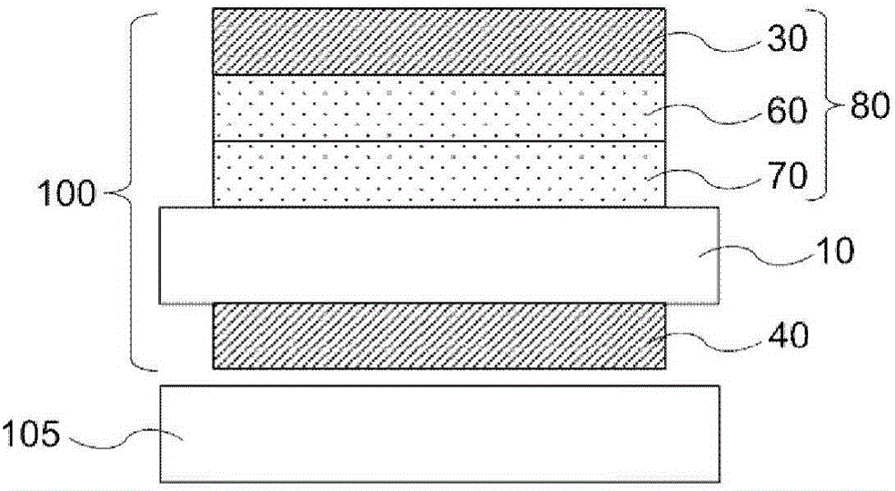
[0093] Polarizing plate, IPS liquid crystal cell (front retardation: 322nm, pretilt angle: 0.1°), second optical anisotropy element (negative A plate of nx=nz>ny; front retardation Re 2 =120nm), the first optical anisotropic element (negative C plate of nx=ny>nz; thickness direction retardation Rth 1 =80nm) and an O-mode liquid crystal display device of a polarizing plate were used as simulation models, and simulations were performed. Both the wavelength dispersion of the retardation of the first optical anisotropic element and the second optical anisotropic element were set to R450 / R550=1.10. The configuration of each optical anisotropic element is as follows Figure 4 shown.

[0094] For the simulation, a simulator for liquid crystal displays "LCD MASTER Ver. 6.084" manufactured by Shintech Co., Ltd. was used. Use the extended function of LCD Master to obtain the contrast in each viewing direction (polar angle θ=0-80°, azimuth angle φ=0-360°) and the chromaticity xy of th...

Embodiment 2~4 and comparative example 3

[0102] Same as in Example 1, using a liquid crystal cell with a pretilt angle of 0°, the thickness direction retardation Rth of the first optical anisotropic element 1 The simulation was carried out by changing to 60 nm and changing the wavelength dispersion R450 / R550 of the retardation of the first optical anisotropic element and the second optical anisotropic element. express the result in Figure 6 middle.

[0103] Depend on Figure 6 As a result, it can be seen that if the optical anisotropic elements have the same retardation value at a wavelength of 550 nm, there is no large change in contrast even if the wavelength dispersion is different. In Comparative Example 3 where both the first optical anisotropic element and the second optical anisotropic element are retarded and the wavelength dispersion R450 / R550=1.02, it can be seen that the area surrounded by the locus on the chromaticity diagram is large and the color shifts Big. In addition, in Comparative Example 3, i...

Embodiment 5~7 and comparative example 4

[0106] Use a liquid crystal cell with a pretilt angle of 0°, use a negative C plate with nx=ny>nz as the first optical anisotropic element, use a positive B plate with nz>nx>ny as the second optical anisotropic element, and change the first The simulation was carried out for the wavelength dispersion R450 / R550 of the retardation of the optical anisotropic element and the second optical anisotropic element. The characteristics and simulation results of the optical anisotropic element used in each example and comparative example are shown in Figure 7 middle.


PUM

PropertyMeasurementUnit
angleaaaaaaaaaa
thicknessaaaaaaaaaa
thicknessaaaaaaaaaa

Abstract

The liquid crystal panel (100) includes a liquid crystal cell (10), a first polarizer (30) on one side of the liquid crystal cell, a second polarizer (40) on the other side of the liquid crystal cell, a first optically anisotropic element (60) having a positive refractive index anisotropy disposed between the liquid crystal cell and the first polarizer, and a second optically anisotropic element (70) having a negative refractive index anisotropy disposed between the first optically anisotropic element and the liquid crystal cell. Liquid crystal molecule in the liquid crystal cell (10) is homogeneously aligned and has a pretilt angle of 0.5 DEG or less in non-electric-field state. At least one of the first optically anisotropic element (60) and the second optically anisotropic element (70) has a ratio R450 / R550 of 1.1 or more, where R550 is a retardation at a wavelength of 550 nm and R450 is a retardation at a wavelength of 450 nm.

Description

technical field [0001] The present invention relates to a liquid crystal panel provided with an optical anisotropy element between a liquid crystal cell and a polarizing plate. In addition, the present invention relates to a liquid crystal display device using the above liquid crystal panel. Background technique [0002] The liquid crystal panel includes a liquid crystal cell between a pair of polarizing plates. In the liquid crystal cell of the in-plane switching (IPS) mode, the liquid crystal molecules are uniformly aligned in a direction approximately parallel to the substrate surface in the state of no electric field, and the liquid crystal molecules are rotated in the plane parallel to the substrate surface by applying a lateral electric field to control the flow of light. Transmission (shown in white) and occlusion (shown in black). A transverse electric field type liquid crystal panel in which liquid crystal molecules are uniformly aligned in a non-electric field st...

Claims


Application Information

Patent Timeline
Patent Type & Authority Applications(China)
IPC IPC(8): G02F1/1335G02F1/13363G02B5/30
CPCG02B5/3083G02F1/133528G02F1/13363G02F1/133531G02F1/133634G02F1/134363G02F2413/02G02F2413/06G02F2413/08G02F2413/10
Inventor 饭田敏行
Owner NITTO DENKO CORP
Why Eureka
Try Eureka