
Scanning method and device for infrared touch screen

A technology of infrared touch screen and scanning method, which is applied in the input/output process of data processing, instruments, electrical and digital data processing, etc. Low computing performance, low cost, and the effect of improving recognition accuracy

Inactive Publication Date: 2016-10-12
GUANGZHOU HUAXIN ELECTRONICS TECH
View PDF3 Cites 11 Cited by
  • Summary
  • Abstract
  • Description
  • Claims
  • Application Information

AI Technical Summary

Problems solved by technology

The occurrence of this problem is related to the algorithm adopted by the existing infrared touch screens. Most of the existing infrared touch screens are based on the results of positive scanning (that is, the signals generated by the transmitting and receiving signals facing each other), and the cutting algorithm is used for coordinate calculation. When the signal is scanned, the position of the touch object cannot be recognized
[0005] Although some touch screens can recognize touch objects that are much smaller than the distance between their own lamp tubes, they need to use image algorithms to perform coordinate calculations. This method leads to a large amount of calculations, and requires the use of ultra-high-performance MCUs or drivers.
This leads to an increase in the final cost of the product

Method used


Image

  • Scanning method and device for infrared touch screen
  • Scanning method and device for infrared touch screen
  • Scanning method and device for infrared touch screen

Examples


Embodiment Construction

[0034] The following will clearly and completely describe the technical solutions in the embodiments of the present invention with reference to the accompanying drawings in the embodiments of the present invention. Obviously, the described embodiments are only some, not all, embodiments of the present invention. Based on the embodiments of the present invention, all other embodiments obtained by persons of ordinary skill in the art without making creative efforts belong to the protection scope of the present invention.

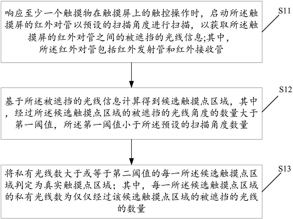
[0035] see figure 1 , is a schematic flowchart of an embodiment of the method for scanning an infrared touch screen provided by the present invention. The scanning method of the infrared touch screen provided in this embodiment includes steps S11-S13, wherein:

[0036] S11. In response to the touch operation of at least one touch object on the touch screen, start the infrared pair tube of the touch screen to scan at a preset scanning angle, so as to obtain th...


PUM


Abstract

The invention discloses a scanning method for an infrared touch screen. The scanning method includes: starting infrared light emitting and receiving diodes of the touch screen to perform scanning at a preset scanning angle during responding to at least one touch control operation of a touch article on the touch screen so as to acquire information of shielded light beams between the infrared light emitting and receiving diodes of the touch screen, wherein the infrared light emitting and receiving diodes includes infrared light emitting diodes and infrared light receiving diodes; calculating candidate touch point zones based on the information of the shielded light beams, wherein the number of angles of the shielded light beams of the candidate touch point zones is greater than a first threshold, and the first threshold is less than a preset number of scanning angles; determining each candidate touch point zone having the number of privately-owned light beams greater than or equal to a second threshold as a true touch point zone, wherein the number of the privately-owned light beams of the each candidate touch point zone is the number of shielded light beams passing the candidate touch point zone.

Description

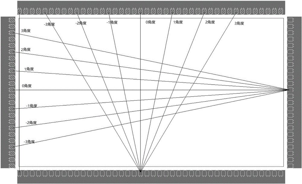
technical field [0001] The invention relates to the technical field of touch screens, in particular to a scanning method and device for an infrared touch screen. Background technique [0002] Now that the touch screen technology is widely used, the scanning method related to the touch screen is becoming more and more important, and its scanning speed affects the recognition accuracy of the touch point on the touch screen to a great extent. [0003] Usually, infrared emitting tubes and infrared receiving tubes are closely arranged on the frame of the infrared paired tube touch screen, and the touch point is identified by scanning whether the infrared paired tube is blocked. [0004] The smallest touch object that can be recognized by the existing infrared touch screen is generally related to the distance between the lamp tubes (infrared tubes). When the touch screen increases the distance between the light tubes in order to reduce costs, the corresponding product performance...

Claims


Application Information

Patent Timeline
Patent Type & Authority Applications(China)
IPC IPC(8): G06F3/042
CPCG06F3/0421
Inventor 刘军刚范威邹超洋
Owner GUANGZHOU HUAXIN ELECTRONICS TECH
Learn More