
Switch cabinet circuit breaker entrance and exit control mechanism

A technology of access control and circuit breaker, applied in substation/switch layout details, electrical components, etc., can solve the problems of electric shock safety hazards, inconvenient maintenance and installation, etc.

Active Publication Date: 2016-10-12
XINJIANG TBEA AUTOMATIC EQUIP
View PDF4 Cites 4 Cited by
  • Summary
  • Abstract
  • Description
  • Claims
  • Application Information

AI Technical Summary

Problems solved by technology

[0002] The switchgear is an important part of the power equipment. The installation of its circuit breaker is usually directly fixed in the circuit breaker room by bolts, which is inconvenient for maintenance and installation. It is in a power-off state, but there is a lot of static electricity in the circuit breaker room, workers need to put their hands into the circuit breaker room during maintenance and installation, and there is a potential safety hazard of electric shock

Method used


Image

  • Switch cabinet circuit breaker entrance and exit control mechanism
  • Switch cabinet circuit breaker entrance and exit control mechanism
  • Switch cabinet circuit breaker entrance and exit control mechanism

Examples


Embodiment Construction

[0020] The principles and features of the present invention are described below in conjunction with the accompanying drawings, and the examples given are only used to explain the present invention, and are not intended to limit the scope of the present invention.

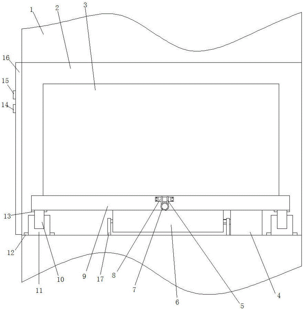
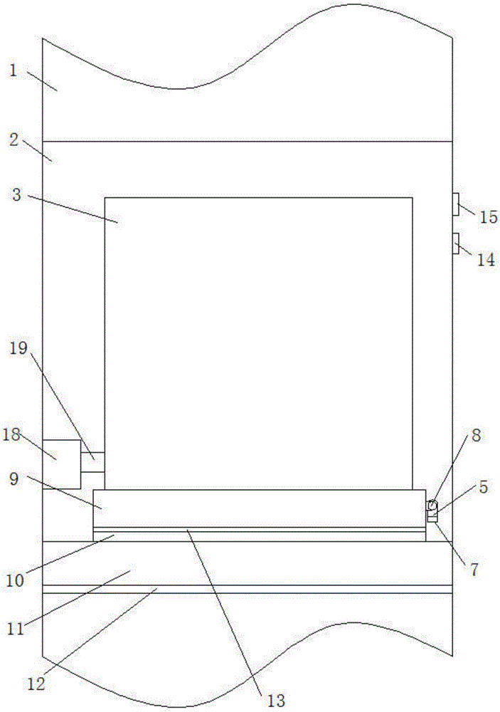
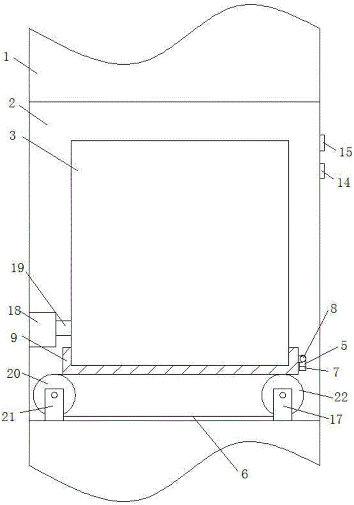
[0021] Such as figure 1 , figure 2 and image 3 As shown, a switch cabinet circuit breaker access control mechanism, the cabinet body 1 is provided with a circuit breaker room 2, the circuit breaker 3 is located in the circuit breaker room 2, and the front side of the circuit breaker room 2 corresponding to the cabinet body 1 is provided with a room door 16. It also includes an external power supply and a motor 4. The bottom of the circuit breaker 3 is fixed with a support frame 9. The bottoms of both sides of the support frame 9 are respectively fixed with strip-shaped sliders 10, and the bottom of the circuit breaker chamber 2 is fixed corresponding to the slider 10. A chute 11 is provided, and the slider 10 is...


PUM


Abstract

The invention relates to a switch cabinet circuit breaker entrance and exit control mechanism. The switch cabinet circuit breaker entrance and exit control mechanism comprises a cabinet body, an externally-arranged power supply and a motor, wherein a circuit breaker chamber is arranged in the cabinet body, a circuit breaker is arranged in the circuit breaker chamber, the front side of the circuit breaker chamber is provided with a chamber door corresponding to the cabinet body, the bottom part of the circuit breaker is fixedly provided with a supporting frame, the supporting frame is fixedly provided with strip-shaped sliding blocks at two sides of the bottom part, sliding grooves are fixedly formed in the bottom part of the circuit breaker chamber in correspondence to the sliding blocks, and the sliding blocks are arranged in the sliding grooves in a slidable manner; a driving wheel and a driven wheel are connected at the bottom part of the circuit breaker chamber and between the sliding grooves on two sides of the supporting frame in a rotated manner; the driving wheel is arranged on one side, away from the chamber door, in the circuit breaker chamber, and the driven wheel is arranged on one side, close to the chamber door, in the circuit breaker chamber; and a conveying belt surrounds the driving wheel and the driven wheel, and the outer side of the conveying belt is pressed against the bottom part of the supporting frame; and the externally-arranged power supply is connected with the motor through a circuit, the motor is installed in the circuit breaker chamber, and an output end of the motor is connected with the driving wheel and drives the driving wheel to rotate forwards and backwards. The switch cabinet circuit breaker entrance and exit control mechanism has the beneficial effects of being simple in structure, convenient in maintenance and installation, and safe and reliable.

Description

technical field [0001] The invention relates to the field of electric equipment, in particular to a switch cabinet circuit breaker access control mechanism. Background technique [0002] The switchgear is an important part of the power equipment. The installation of its circuit breaker is usually directly fixed in the circuit breaker room by bolts, which is inconvenient for maintenance and installation. It is in a power-off state, but there is a lot of static electricity in the circuit breaker room. Workers need to put their hands into the circuit breaker room during maintenance and installation, which may pose a safety hazard of electric shock. Contents of the invention [0003] The technical problem to be solved by the present invention is to provide a switchgear circuit breaker access control mechanism with simple structure, convenient maintenance and installation, safe and reliable. [0004] The technical solution of the present invention to solve the above-mentioned ...

Claims


Application Information

Patent Timeline
IPC IPC(8): H02B1/36
CPCH02B1/36
Inventor 车晓明
Owner XINJIANG TBEA AUTOMATIC EQUIP
Learn More