Reactive power partition method based on reactive power source-charge numbers and community mining

A technology of voltage partitioning and load intermediary, applied in reactive power compensation, AC network voltage adjustment, circuit devices, etc., can solve the problem of weak reactive power coupling between reactive power source and load node

Active Publication Date: 2016-10-12
CHONGQING UNIV
View PDF4 Cites 9 Cited by
  • Summary
  • Abstract
  • Description
  • Claims
  • Application Information

AI Technical Summary

Problems solved by technology

[0004] The purpose of the present invention is to address the shortcomings of the existing community mining method for reactive power and voltage partitioning methods in power systems, and propose a reactive power and voltage partitioning method based on reactive source-load betweenness and community mining, which can In the partition process, considering the influence of the reactive power output by the reactive power source on the reactive load through the transmission path between the reactive source-load node pair, the reactive power coupling of the reactive power source-load node in the partition can be strong, The reactive power coupling between reactive power sources and load nodes between partitions is weak. On the basis of ensuring the reactive power balance in the partition, the global optimality of the partition is ensured from the perspective of reactive power transmission, so as to ensure the reactive power and voltage partition of the power system. In order to provide a reliable scientific basis for reactive voltage control

Method used


Image

  • Reactive power partition method based on reactive power source-charge numbers and community mining
  • Reactive power partition method based on reactive power source-charge numbers and community mining
  • Reactive power partition method based on reactive power source-charge numbers and community mining

Examples


Embodiment

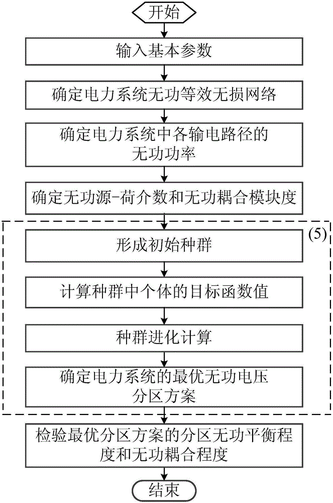
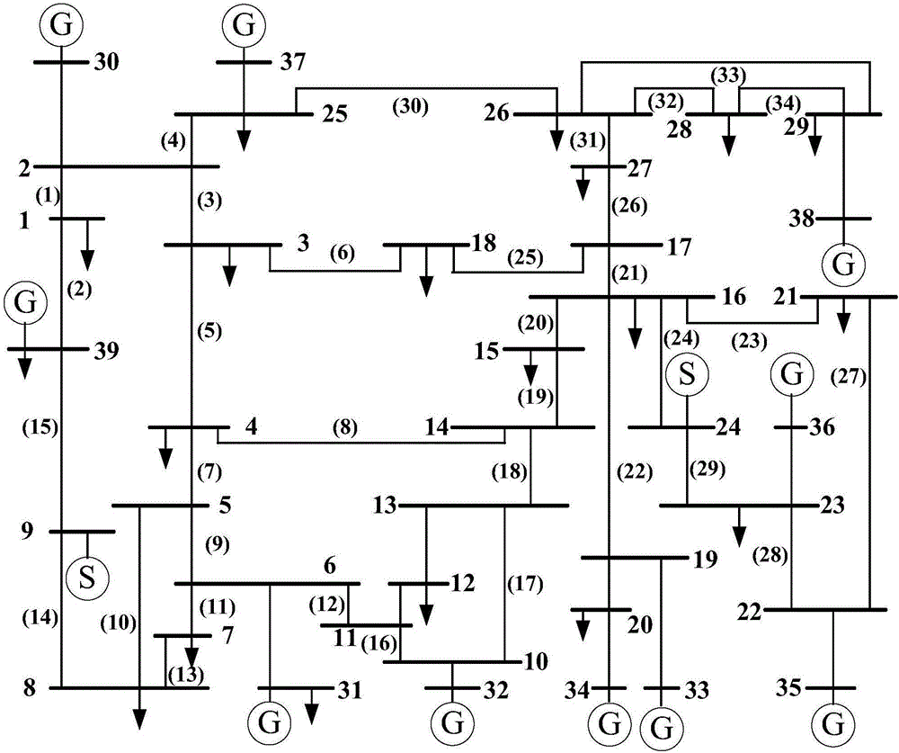
[0104] like figure 1 and figure 2 As shown, the specific steps of a reactive voltage partition method based on reactive source-load betweenness and community mining are as follows:

[0105] (1) Input basic parameters

[0106] First, input the basic parameters required for calculation, including the basic parameters of the power system and the parameters of the traditional genetic algorithm. The basic parameters of the power system include the total number of nodes, node number, node type, corresponding voltage level of nodes, active power load and reactive power load of each node, number of nodes connected to generators, active power and reactive power output by each generator. Work power, node number at the beginning and end of each line, line resistance, line reactance and line susceptance, node number of each transformer, transformer transformation ratio, transformer resistance and transformer reactance, the reference voltage is 345kV and the reference power is 100MVA. ...


PUM


Abstract

The invention provides a reactive power partition method based on reactive power source-charge numbers and community mining and belongs to the technical field of power system automation. Basic parameters are input through programs by means of a computer, then a power system reactive equivalent lossless network is determined, then reactive power, reactive source-charge numbers and reactive coupling modularity of all power transmission routes in a power system are determined, the optimal reactive voltage partition of the power system is determined by means of the traditional genetic algorithm, and finally the partition reactive coupling degree and the reactive balance degree of the optimal partition scheme are inspected. The method has the advantages that in the reactive voltage partition process, influences of reactive power output by a reactive power source on reactive loads through the transmission routes between reactive source-load node pairs are taken into consideration, reactive coupling performance of reactive source-load nodes in partitions can be strong, reactive coupling performance of the reactive source-load nodes between the partitions can be weak, and on the basis that reactive balance in the partitions is guaranteed, global optimality of the partitions is ensured from the perspective of reactive transmission. The method can be widely used in the reactive voltage partitions of the power system and provides scientific bases for reactive voltage control of the power system.

Description

technical field [0001] The invention belongs to the technical field of power system automation, and in particular relates to a reactive voltage partition method based on reactive source-load intermediary and community mining. Background technique [0002] The reactive voltage problem of the power system has an important impact on the voltage quality and safe operation of the power system. The reactive power of the distributed voltage control system and the voltage of the regulation system can ensure the reactive power balance within the partition and the voltage of each node to meet the operating requirements. Therefore, the reactive power and voltage hierarchical partition control of the interconnected power system is to ensure the reliable, high-quality and economical operation of the system. One of the important measures. As the basis of hierarchical voltage control, reactive power and voltage partitions require strong reactive power coupling within the partitions and we...

Claims


Application Information

Patent Timeline
Patent Type & Authority Applications(China)
IPC IPC(8): H02J3/16
CPCH02J3/16H02J2203/20Y02E40/30
Inventor 王韶黄晗尹洪涛张文龙邓先芳汪俊宇张成瑜黄驰
Owner CHONGQING UNIV
Why Eureka
Try Eureka