
Organic electroluminescence material containing phenanthrene structure and organic luminescence device thereof

An organic light-emitting device and luminescent technology, applied in the direction of luminescent materials, electric solid devices, electrical components, etc., can solve the problems of low lifespan and low luminous efficiency, and achieve wide energy gap, high luminous efficiency, and carrier transport balance Effect

Inactive Publication Date: 2018-09-11
CHANGCHUN HYPERIONS TECH CO LTD
View PDF0 Cites 1 Cited by
  • Summary
  • Abstract
  • Description
  • Claims
  • Application Information

AI Technical Summary

Problems solved by technology

For commonly used anthracene-based fluorescent blue light materials, the luminous efficiency is low; for phosphorescent blue light materials such as Firpic, the lifetime is low

Method used


Image

  • Organic electroluminescence material containing phenanthrene structure and organic luminescence device thereof
  • Organic electroluminescence material containing phenanthrene structure and organic luminescence device thereof
  • Organic electroluminescence material containing phenanthrene structure and organic luminescence device thereof

Examples


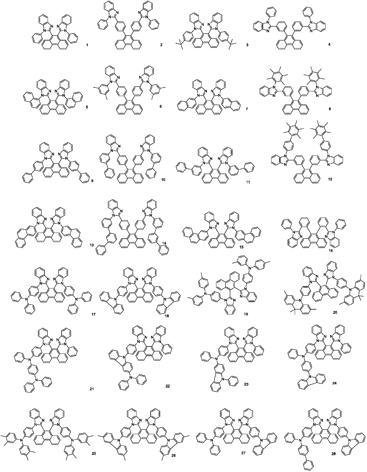
Embodiment 1

[0076] Embodiment 1: the preparation of compound 1

[0077]

[0078] Step1. Dissolve 1-3, 100mmol in anhydrous THF, cool to -78°C, add 150mmol of n-butyllithium dropwise, react at this temperature for 1 hour, add 2 equivalents of DMF, gradually raise the temperature to 0°C, and react Overnight, after the reaction was completed, 500 mmol of deionized water was added. After the reaction was completed, DCM was added for extraction, the organic phase was spin-dried, and column chromatography was performed to obtain the product 1-2, 70 mmol.

[0079] Step2. Products 1-2, 70mmol, 1-1, 140mmol, dissolved in a mixed solvent of DMF and water at a ratio of 9:1 (v / v), heated to 80 degrees Celsius, fed with oxygen, stirred and reacted for 6 hours, after the reaction was completed , the organic phase was spin-dried and subjected to column chromatography to obtain 35 mmol of the product.

Embodiment 2

[0080] Embodiment 2: the preparation of compound 2

[0081]

[0082] Step1. Under the protection of nitrogen, take 1-3, 100mmol, 100mmol of p-chlorophenylboronic acid, 300mol of potassium carbonate, 1mol of tetraphenylphosphopalladium, a mixed solvent of toluene, ethanol and water for ultrasonic deoxygenation, stir and dissolve, and replace the air three times , Reflux reaction for 6h. Cool to room temperature, add enough dichloromethane to completely dissolve the product, pass through a small amount of silica gel funnel, and remove catalyst and salt. The filtrate was concentrated to a viscous state and subjected to column chromatography to obtain product 2-3, 85 mmol.

[0083] Step2. Dissolve 2-3, 85mmol in anhydrous THF, cool to -78°C, add 100mmol of n-butyllithium dropwise, react at this temperature for 1 hour, add 2 equivalents of DMF, gradually raise the temperature to 0°C, and react Overnight, after the reaction was completed, 200 mmol of deionized water was added. ...

Embodiment 3

[0085] Embodiment 3: the preparation of compound 5

[0086] With embodiment 1.


PUM


Abstract

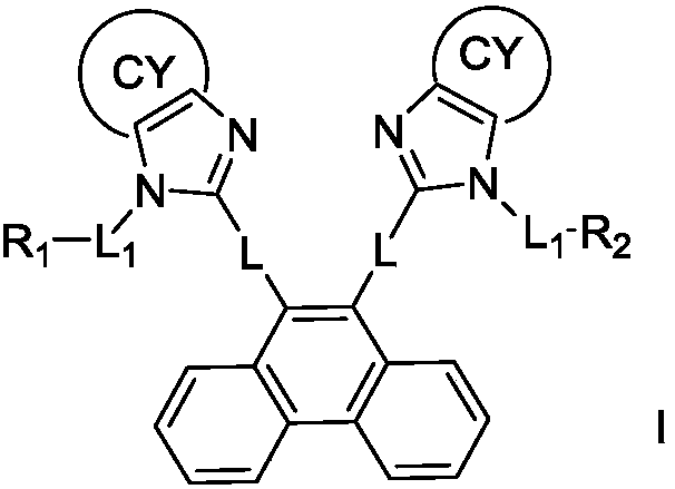
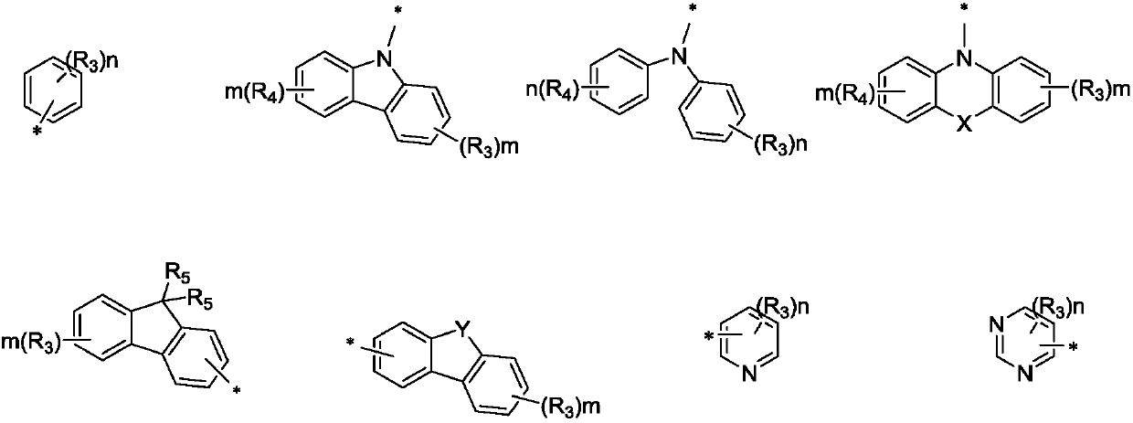
The invention provides an organic electroluminescence material containing a phenanthrene structure and an organic luminescence device thereof, and belongs to the technical field of organic photoelectric materials. The structure of the organic electroluminescence material containing the phenanthrene structure contains the phenanthrene ring structure, wherein the phenanthrene ring structure is a blue ray structure which is excellent in performance and has a higher triplet state energy level and a wider energy gap, and in molecules, through connection with benzimidazole groups, the electron transportation capability of the blue ray main structure is enhanced, so that carrier transportation is balanced. Compared with the prior art, the material has the advantages that the material is applied to the organic luminescence device and especially used as the blue luminescence material in a luminescence layer, the luminescence efficiency is relatively high, and the driving voltage is relatively low.

Description

technical field [0001] The invention relates to the technical field of organic photoelectric materials, in particular to an organic electroluminescent material containing a phenanthrene structure and an organic light emitting device thereof. Background technique [0002] Organic electroluminescence refers to the phenomenon that organic materials are excited by electric current and electric field to emit light under the action of electric field. Organic light-emitting diodes (OLEDs) are a next-generation display technology that utilizes this phenomenon to realize displays. Since Tang C.W. and Vanslyke S.A. of American Kodak Company produced the first organic electroluminescent device with excellent performance in 1987, organic electroluminescent displays have attracted great interest due to their advantages. [0003] At present, due to their excellent performance, red and green light-emitting materials have been used commercially, while the wide energy gap and high thermal s...

Claims


Application Information

Patent Timeline
IPC IPC(8): C07D235/20C07D403/14C07D401/14C07D405/14C07D409/14C07D413/14C07D417/14C09K11/06H01L51/50H01L51/54
CPCC09K11/06C07D235/20C07D401/14C07D403/14C07D405/14C07D409/14C07D413/14C07D417/14C09K2211/1007C09K2211/1014C09K2211/1011C09K2211/1029C09K2211/1033C09K2211/1044C09K2211/1037C09K2211/1088C09K2211/1092H10K85/615H10K85/631H10K85/636H10K85/654H10K85/657H10K85/6572H10K85/6576H10K85/6574H10K50/11
Inventor 孙可一蔡辉
Owner CHANGCHUN HYPERIONS TECH CO LTD
Learn More