Motor blank

A technology for punching and punching motors, which is applied in the direction of electrical components, electromechanical devices, electric components, etc., can solve the problems of motor efficiency reduction, high-frequency harmonics, and noise increase, so as to improve efficiency and reduce magnetic flux leakage coefficient , noise reduction effect

Inactive Publication Date: 2016-10-12
青岛海联金汇电机有限公司
View PDF5 Cites 2 Cited by
  • Summary
  • Abstract
  • Description
  • Claims
  • Application Information

AI Technical Summary

Problems solved by technology

But this will face new problems: this approach will lead to the air gap magnetic field, and the uneven distribution of the air gap flux density will cause more high-frequency harmonics during the operation of the motor, which will reduce the efficiency of the motor and increase the noise

Method used


Image

  • Motor blank
  • Motor blank
  • Motor blank

Examples


Embodiment 1

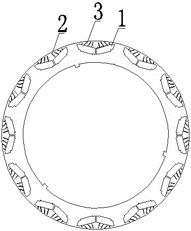
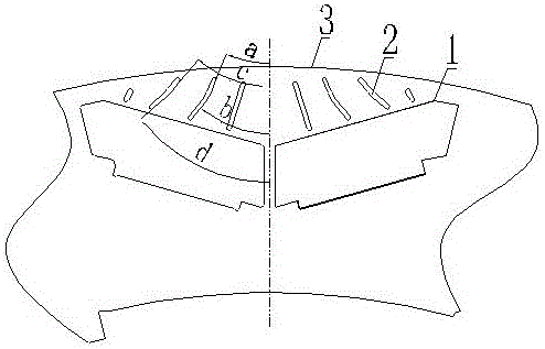
[0015] As shown in the figure, this embodiment includes a punching body 3, and the punching body has 12 or more magnetic steel hole groups distributed along its circumferential direction, and each magnetic steel hole group includes two V-shaped distribution holes with openings outward. Corresponding to each magnetic steel hole group, there are two sets of magnetic force line guide holes 2 symmetrically distributed. Each magnetic flux guide hole 2 is a straight line or a broken line or an arc, or a combination of at least two of the above. Each magnetic force line guide hole 2 is in the shape of converging toward the axial direction of the magnetic steel hole group from the inside of the punch body to the outside. In this embodiment, there are eight magnetic force line guide holes 2 corresponding to each magnetic steel hole group. The middle pair of magnetic force line guide holes 2 is a straight line with an angle of 19° with the axis of the magnetic steel hole group. The ou...

Embodiment 2

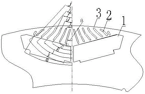
[0017] As shown in the figure, this embodiment includes a punching body 3, and the punching body has 12 or more magnetic steel hole groups distributed along its circumferential direction, and each magnetic steel hole group includes two V-shaped distribution holes with openings outward. Corresponding to each magnetic steel hole group, there are two sets of magnetic force line guide holes 2 symmetrically distributed. Each magnetic flux guide hole 2 is a straight line or a broken line or an arc, or a combination of at least two of the above. Each magnetic force line guide hole 2 is in the shape of converging toward the axial direction of the magnetic steel hole group from the inside of the punch body to the outside. In this embodiment, there are fourteen magnetic force line guide holes 2 corresponding to each magnetic steel hole group. The innermost pair of magnetic force line guide holes 2 is a straight line with an included angle of a=19° with the axis of the magnetic steel ho...


PUM


Abstract

The invention belongs to the technical field of motors, and particularly relates to a new permanent magnet variable frequency motor rotor blank structure. According to the adopted technical scheme, the motor blank comprises a blank body; at least one magnetic steel hole group is arranged in the blank body; each magnetic steel hole group is composed of two V-shaped holes; and a magnetic line guide hole is arranged between each magnetic steel hole group and the edge of the blank body. After the magnetic steel is mounted, the direction of the magnetic line can be guided through the magnetic line guide hole, the magnetic flux leakage coefficient is reduced, and the motor efficiency is improved. Meanwhile, the magnetic line guide hole can reduce noise generated when the motor operates.

Description

technical field [0001] The invention belongs to the technical field of motors, and in particular relates to a new rotor punching structure of a permanent magnet variable frequency motor. Background technique [0002] The embedded rotor is the rotor form with the highest flux leakage coefficient, which affects the efficiency of the motor. In order to strengthen the magnetism, V-shaped punching or V+ one-type punching structure is generally used now to improve the efficiency of the motor. But this will face new problems: this approach will lead to air gap magnetic field, and the uneven distribution of air gap magnetic density will cause more high frequency harmonics during the operation of the motor, which will reduce the efficiency of the motor and increase the noise. Contents of the invention [0003] In view of the above problems, the present invention provides a permanent magnet variable frequency motor rotor stamping that can improve motor efficiency and reduce motor op...

Claims


Application Information

Patent Timeline
Patent Type & Authority Applications(China)
IPC IPC(8): H02K1/27
CPCH02K1/2706H02K2213/03
Inventor 刘国平曹庆钢于铁军王珍超孟庆亮李臣升
Owner 青岛海联金汇电机有限公司
Why Eureka
Try Eureka