Anti-harmonic interference device for carrier aggregation, antenna device and mobile terminal
A technology of harmonic interference and carrier aggregation, applied in transmission noise suppression, electrical components, transmission systems, etc., can solve the problems of high cost and large size of power amplifier, and achieve the effect of simple structure, elimination of harmonic interference, and low cost
- Summary
- Abstract
- Description
- Claims
- Application Information
AI Technical Summary
Problems solved by technology
Method used
Image
Examples
Embodiment 1
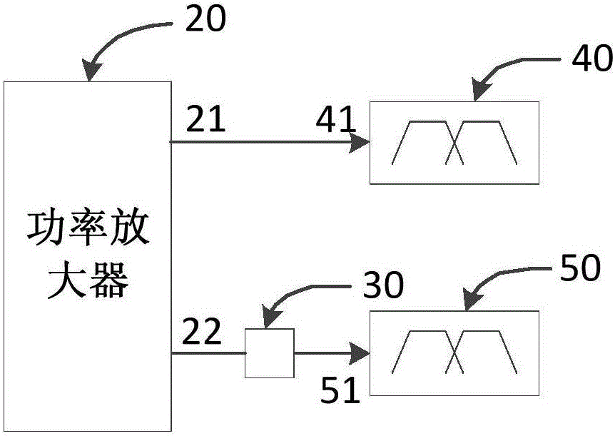
[0025] image 3 It is a schematic structural diagram of an anti-harmonic interference device for carrier aggregation provided in Embodiment 1 of the present invention. Such as image 3 As shown, the anti-harmonic interference device includes: a power amplifier 20 , a first filtering unit 30 , a first duplexer 40 and a second duplexer 50 .
[0026] The sending terminal 41 of the first duplexer 40 is connected with the first uplink interface 21 that sends the uplink signal of the first frequency band in the power amplifier 20, and the receiving terminal is used to send the downlink signal of the first frequency band to the wireless transceiver; the antenna terminal is used for The signal transmission of the first frequency band signal is performed with the antenna.
[0027] The sending terminal 51 of the second duplexer 50 is connected to the second uplink interface 22 that sends the uplink signal of the second frequency band in the power amplifier 20 through the first filteri...
Embodiment 2
[0038] Figure 5 It is a schematic diagram of a working process of a carrier aggregation anti-harmonic interference device provided by Embodiment 2 of the present invention. Such as Figure 5 As shown, the anti-harmonic interference device includes: a power amplifier 20 , a first filtering unit 30 , a first duplexer 40 , a second duplexer 50 , a third duplexer 80 and a second filtering unit 90 .
[0039] The sending terminal 81 of the third duplexer 80 is connected to the third uplink interface 23 that sends the uplink signal of the third frequency band in the power amplifier 20 through the second filtering unit 90, and the receiving terminal 82 is used to send the third frequency band to the wireless transceiver 10 the downlink signal; the antenna terminal 83 is used for signal transmission of the third frequency band signal with the antenna 70 .
[0040] The frequency of the harmonics of the uplink signal in the first frequency band overlaps with the frequency of the downlin...
Embodiment 3
[0048] An embodiment of the present invention provides an antenna device, Figure 6 It is a schematic structural diagram of an antenna device provided in Embodiment 3 of the present invention, refer to Figure 6 , the antenna device includes the anti-harmonic interference device 100 described in any embodiment of the present invention, a wireless transceiver 10 and an antenna 70 .
[0049] The wireless transceiver 10 includes multiple downlink interfaces for receiving downlink signals of multiple frequency bands, and the multiple downlink interfaces are connected to receiving terminals of corresponding duplexers in the anti-harmonic interference device 100 . The antenna 70 is connected to antenna terminals of a plurality of duplexers of the anti-harmonic interference device 100 .
[0050] Exemplary, refer to Figure 6 , the wireless transceiver 10 is used to send and receive signals of different frequency bands, and has a corresponding uplink interface and downlink interface...
PUM
 Abstract
Description
Claims
Application Information
 - R&D
- Intellectual Property
- Life Sciences
- Materials
- Tech Scout
- Unparalleled Data Quality
- Higher Quality Content
- 60% Fewer Hallucinations
Browse by: Latest US Patents, China's latest patents, Technical Efficacy Thesaurus, Application Domain, Technology Topic, Popular Technical Reports.
© 2025 PatSnap. All rights reserved.Legal|Privacy policy|Modern Slavery Act Transparency Statement|Sitemap|About US| Contact US: help@patsnap.com


