Unlock instant, AI-driven research and patent intelligence for your innovation.

Transmission device

一种变速装置、部件的技术,应用在动力装置、传动装置零件、运输和包装等方向,能够解决生产率差、无法应用拉削加工、难以确保小齿轮支承部良好润滑等问题,达到良好润滑的效果

Active Publication Date: 2016-10-12
AISIN AW CO LTD +1
View PDF5 Cites 0 Cited by
  • Summary
  • Abstract
  • Description
  • Claims
  • Application Information

AI Technical Summary

Problems solved by technology

[0004] In such a structure, when the carrier (c2) forms the spline engagement portion (sp) that engages with the cylindrical shaft member (ch), the contact portion of the race (c2R) becomes a physical obstacle, so it cannot be applied. Broaching
Therefore, molding processing is required, and there is a problem of poor productivity
On the other hand, if only the protruding length of the race abutting portion (c2R) inward in the radial direction is kept short, the oil receiving portion (or) is shallow and cannot receive a sufficient amount of oil. As a result, it is difficult to ensure Good lubrication of the bearing part of the pinion (p2)

Method used


Image

  • Transmission device
  • Transmission device
  • Transmission device

Examples


Embodiment Construction

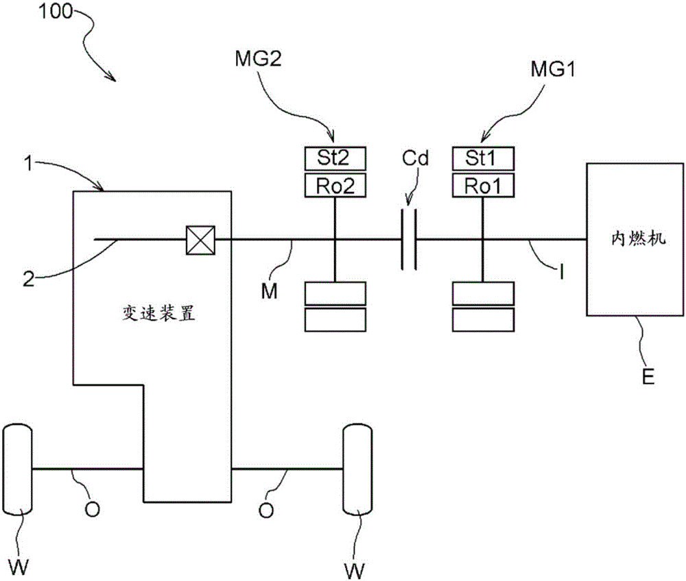
[0024] Embodiments of the transmission will be described with reference to the drawings. In this embodiment, the transmission device 1 incorporated in the vehicle drive device 100 will be described as an example. The vehicle drive device 100 of the present embodiment is a vehicle drive device (hybrid vehicle) for driving a vehicle (hybrid vehicle) including both an internal combustion engine E and a rotary electric machine MG as a driving force source for the wheels W of the vehicle. drive unit). In the present embodiment, the vehicle drive device 100 is configured as a two-motor serial / parallel drive device for a hybrid vehicle.

[0025] In addition, "rotating electrical machine MG" is used as a concept including the first rotating electrical machine MG1 and the second rotating electrical machine MG2. In addition, the concept of "rotating electric machine" includes any one of a motor (electric motor), a generator (generator), and a motor generator that functions as both the...


PUM


Abstract

This transmission device is provided with a transmission shaft (2), a cylindrical shaft member (3) and a planetary gear mechanism having a carrier. An in-shaft oil path (21) is formed in the transmission shaft (2). A radially inner portion (IP) of the carrier and the cylindrical shaft member (3) are linked by splines, an inside opening (55) of an induction oil path (51) is formed in a non-spline portion (NP) in the radially inner portion (IP), and a target race member (61) of a thrust bearing (60) is arranged abutting against the carrier. The radially innermost position of the non-spline portion (NP) is located radially outside of the radially outermost position of the spline engagement area (A), and the cylindrical shaft member (3), the non-spline portion (NP) and the target race member (61) form an oil receiving area (OR).

Description

technical field [0001] The present invention relates to a transmission including a planetary gear mechanism having a carrier. Background technique [0002] As a transmission device as described above, a device described in Japanese Patent Application Laid-Open No. 2007-270865 (Patent Document 1) is known. Hereinafter, the patent document 1 image 3 as the application Figure 6 Reprinted, the structure disclosed in Patent Document 1 will be described with reference to this figure. Such as Figure 6 As shown, the transmission device of Patent Document 1 includes a planetary gear mechanism (PG2) arranged coaxially with the propeller shaft (3), and the planetary gear mechanism (PG2) includes a planetary carrier (c2) that rotatably supports the pinion gear (p2). ). Furthermore, the transmission device has a structure that guides the oil supplied through the inside of the propeller shaft (3) toward the carrier shaft (ca) and lubricates the support portion of the pinion (p2) of...

Claims


Application Information

Patent Timeline
Patent Type & Authority Applications(China)
IPC IPC(8): F16H57/04F16H57/08
CPCF16H57/08F16H57/04F16H57/0426F16H57/043F16H57/0471Y10S903/945B60K6/365B60K6/442B60K6/547B60Y2200/92B60Y2306/03B60Y2400/73F16D1/06F16H57/0025F16H57/0479F16H57/0484F16H57/082
Inventor 三好克典佐佐木贤治大室圭佑奥田弘一山本真史今井惠太
Owner AISIN AW CO LTD
Features
  • R&D
  • Intellectual Property
  • Life Sciences
  • Materials
  • Tech Scout
  • Unparalleled Data Quality
  • Higher Quality Content
  • 60% Fewer Hallucinations
Learn More