Contactless power supply system and power transmission device

A power supply system, non-contact technology, applied in circuit devices, control devices, transportation and packaging, etc., can solve problems such as vehicle movement

Active Publication Date: 2018-04-24
NISSAN MOTOR CO LTD
View PDF6 Cites 0 Cited by
  • Summary
  • Abstract
  • Description
  • Claims
  • Application Information

AI Technical Summary

Problems solved by technology

In such a non-contact power supply system, when the vehicle is parked at the power supply position to perform power supply, there are cases where the vehicle moves from the power supply position

Method used


Image

  • Contactless power supply system and power transmission device
  • Contactless power supply system and power transmission device
  • Contactless power supply system and power transmission device

Examples


Embodiment Construction

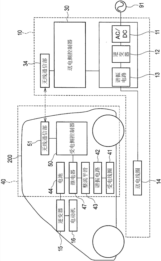
[0026] Hereinafter, embodiments of the present invention will be described with reference to the drawings. figure 1 It is a block diagram showing the configuration of the contactless power supply system according to the present invention. Such as figure 1 As shown, a vehicle 200 includes a power receiving device 40 , and a power transmitting device 10 for supplying electric power to the vehicle 200 is installed in a space on the ground side where the vehicle 200 is parked. The power transmission device 10 includes an AC / DC converter 11 that rectifies an AC voltage supplied from an AC power source 91 , an inverter circuit 12 , a resonant circuit 13 , and a power transmission coil 14 . The power transmission device 10 further includes a power transmission-side controller 30 .

[0027] The power receiving device 40 includes a power receiving coil 41 , a resonant circuit 42 , a rectification smoothing circuit 43 , a relay 47 , and a battery 44 . The power receiving device 40 fu...


PUM


Abstract

A power transmitting device (10) having a power transmitting coil (14) and a power receiving device (40) having a power receiving coil (41) are provided. Then, electric power is transmitted from the power transmitting coil (14) to the power receiving coil (41) in a non-contact manner, and electric power is supplied to a battery (44) mounted on the power receiving device (40). The power transmission device (10) includes: a power factor calculation unit (31) that calculates a power factor (cosθ) based on a phase difference between a voltage and a current supplied to the power transmission coil (14); and a control amount calculation unit (29), It controls the power supplied to the power transmission coil (14) based on the power command value (Pbat*), and performs a function of suppressing the power supplied to the power transmission coil (14) when the power factor is equal to or less than a preset threshold power factor. Control of supplied power. Therefore, when the position of the power receiving coil (41) is displaced relative to the power transmitting coil (14), it is possible to immediately suppress the power to be transmitted.

Description

technical field [0001] The present invention relates to a contactless power supply system and a power transmission device for supplying electric power to a vehicle equipped with a battery, such as an electric car, in a contactless manner. Background technique [0002] A non-contact power supply system has been proposed that supplies electric power to an electrical load mounted on a vehicle by supplying electric power from a power transmitting device installed on the ground side to a power receiving device installed on the vehicle side in a contactless manner. In such a non-contact power supply system, when the vehicle is parked at the power supply position to perform power supply, there are cases where the vehicle moves from the power supply position. In such a case, a misalignment occurs between the power transmitting coil and the power receiving coil, so it is necessary to immediately detect this misalignment to stop the supply of electric power. [0003] As a technique f...

Claims


Application Information

Patent Timeline
Patent Type & Authority Patents(China)
IPC IPC(8): H02J50/12H02J50/80B60L11/18
CPCH02J50/80Y02T90/12Y02T10/7072Y02T90/14B60L53/12B60L53/64B60L53/305Y02T10/70Y02T90/16H02J50/10B60L2210/40B60L2210/30B60L2240/549B60L2240/547B60Y2200/91H02J50/12H02J50/90H02J7/00034
Inventor 冈本智史
Owner NISSAN MOTOR CO LTD
Why Eureka
Try Eureka