Vehicle and vehicle control method

A technology for vehicles and control devices, which can be applied to control drives, control devices, vehicle components, etc., and can solve problems such as research

Active Publication Date: 2017-12-26
HONDA MOTOR CO LTD
View PDF2 Cites 0 Cited by
  • Summary
  • Abstract
  • Description
  • Claims
  • Application Information

AI Technical Summary

Problems solved by technology

However, there is still room for improvement in the method of utilizing the first relationship to the third relationship
For example, in US 2014 / 0191689 A1, there is no detailed study on the use of the first relationship on the basis of the second relationship and the third relationship
[0005] In addition, regarding power priority control, in US 2014 / 0191689 A1, the case where the sum P1+P2 of the power of the left and right motors is zero is mainly explained ([0197], [0217]), but for the sum of power P1+P2 There is still room for research when P2 is not zero

Method used


Image

  • Vehicle and vehicle control method
  • Vehicle and vehicle control method
  • Vehicle and vehicle control method

Examples


Embodiment approach

[0025] A. Structure

[0026] A-1. Overall structure

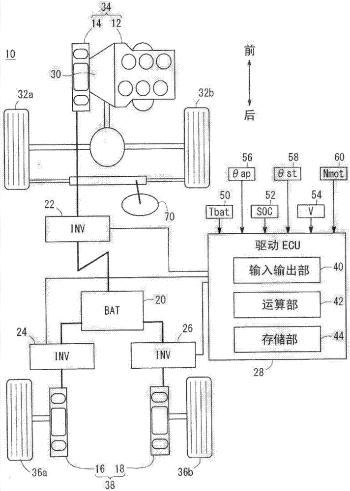
[0027] figure 1 It is a schematic configuration diagram of a drive system of a vehicle 10 and its surroundings according to an embodiment of the present invention. like figure 1 As shown, the vehicle 10 has an engine 12 and a first travel motor 14 arranged in series on the front side of the vehicle 10, a second travel motor 16 and a third travel motor 18 arranged on the rear side of the vehicle 10, and a high-voltage battery 20 (hereinafter referred to as "Battery 20."), the first inverter 22, the second inverter 24, and the third inverter 26, and the driving electronic control unit 28 (hereinafter referred to as "driving ECU28" or "ECU28"). .

[0028]Hereinafter, the first travel motor 14 is referred to as "the first motor 14", "the motor 14", or "the front side motor 14". In addition, the second travel motor 16 is referred to as "second motor 16", "left side motor 16", "motor 16", or "rear side motor 16". The third ...


PUM


Abstract

The present invention provides a vehicle (10) and a control method thereof, wherein the motor control device (28) is based on the supplyable power (β) of the power source (20), and the left motor (16) and the right motor (18) respectively The power loss (L1, L2) corresponding to the rotation state quantity (Nmot), the target power difference (ΔTT) of the left motor (16) and the right motor (18), the target power sum of the left motor (16) and the right motor (18) (TRT_req) to set target left power (TM1) and target right power (TM2), and use target left power (TM1) and target right power (TM2) to control left motor (16) and right motor (18).

Description

technical field [0001] The present invention relates to a vehicle including a left motor mechanically connected to a left wheel and a right motor mechanically connected to a right wheel, and a control method thereof. Background technique [0002] US Patent Application Publication No. 2014 / 0191689 (hereinafter referred to as "US 2014 / 0191689 A1") discloses power control of left and right motor generators (electric motors) in a vehicle. That is, in US 2014 / 0191689 A1, a first relationship including the sum of the left wheel torque etc. and the right wheel torque etc., a second relationship including the difference between the left wheel torque etc. and the right wheel torque etc. are assumed, and A third relationship including the sum of the left power generated or consumed by the left motor generator and the right power generated or consumed by the right motor generator is included (claim 1). Furthermore, based on at least one of the first relationship and the second relatio...

Claims


Application Information

Patent Timeline
Patent Type & Authority Patents(China)
IPC IPC(8): B60K6/46B60K6/52B60K7/00B60K17/356B60W10/08B60W20/00B60W30/18B60L15/20
CPCB60K6/46B60K6/52B60L15/20B60W10/08B60W20/00B60K7/0007B60W30/045B60W30/18145B60W2710/086B60K5/04B60K17/356B60K2005/003Y02T10/84B60L2240/545B60W2510/244B60W2510/246B60W2720/406B60L15/2036Y02T10/40Y02T10/62Y02T10/72B60K1/02Y02T10/64Y02T10/70
Inventor 安藤义纪塚本宗纪野口真利
Owner HONDA MOTOR CO LTD
Why Eureka
Try Eureka