Bending piece detection equipment

A technology for testing equipment and bending parts, applied in metal processing equipment, metal processing, manufacturing tools, etc., can solve the problems of equipment detection efficiency reduction, achieve high automation, improve work efficiency, and ensure accuracy

Active Publication Date: 2016-10-26
德坤精密五金科技(苏州)有限公司
View PDF11 Cites 11 Cited by
  • Summary
  • Abstract
  • Description
  • Claims
  • Application Information

AI Technical Summary

Problems solved by technology

[0004] However, the above-mentioned bending piece detection equipment and most of the existing equipment for bending piece detection, when defective products are detected, the equipment will stop and alarm, and the bending piece will be removed manually. If the staff cannot find the alarm of the machine in time, the equipment will be in a shutdown state, which will easily lead to a great reduction in the detection efficiency of the equipment

Method used


Image

  • Bending piece detection equipment
  • Bending piece detection equipment
  • Bending piece detection equipment

Examples


Embodiment 1

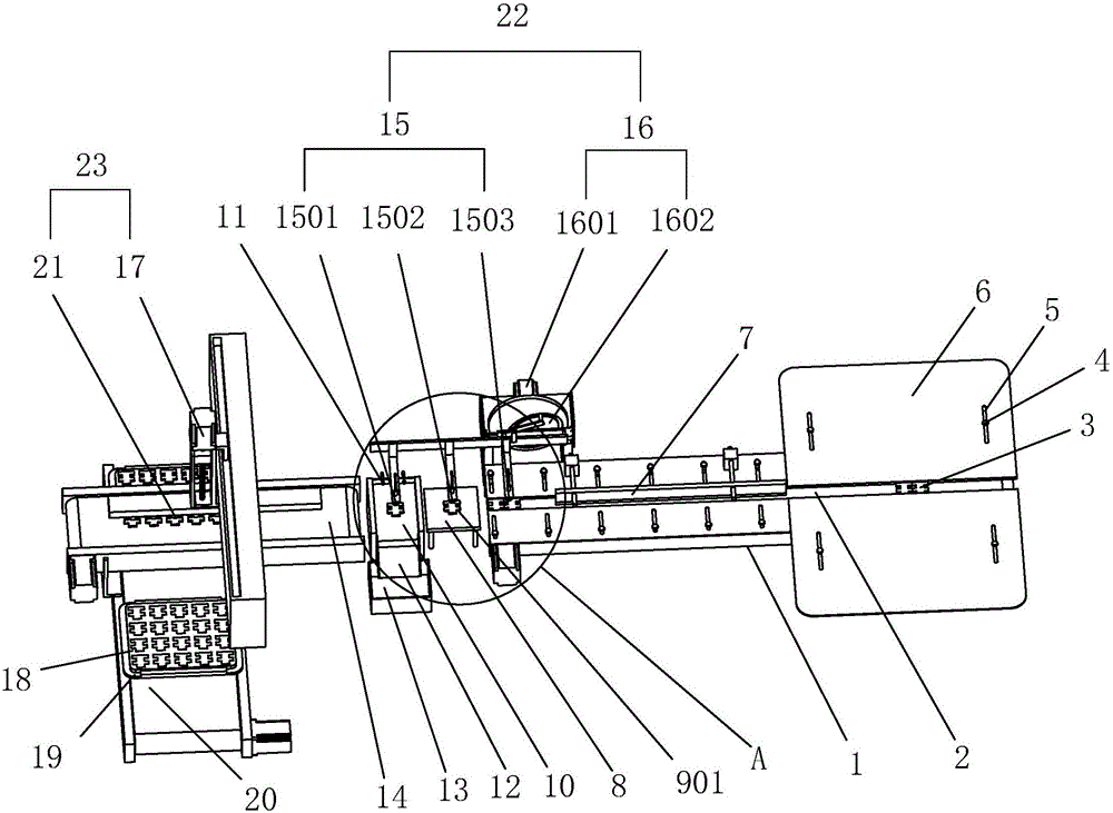
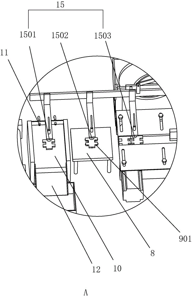
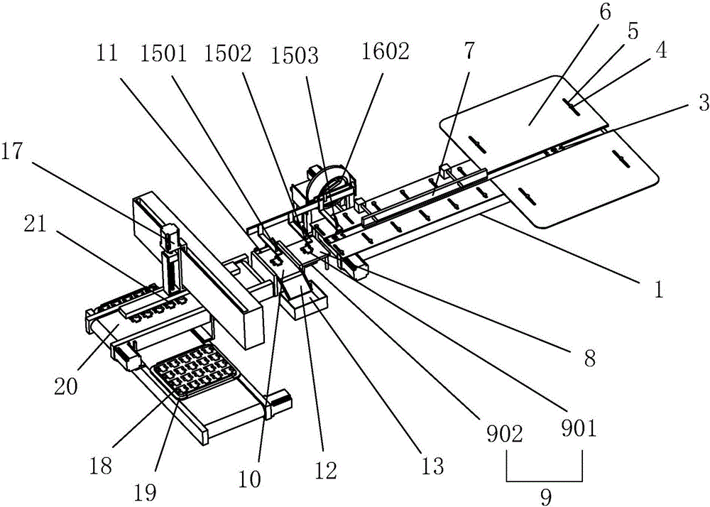
[0033] Embodiment 1: A kind of bending piece detection equipment, such as figure 1 and figure 2Shown, comprise frame 1, be provided with the feeding mechanism that is used for workpiece 3 feeding on frame 1, feed mechanism includes feed conveyer belt 2 and the drive motor that drives feed conveyer belt 2 to convey workpiece 3 (not shown in the figure ), drive the motor to work, and transfer the workpiece 3 on the feed conveyor belt 2 from one end of the feed conveyor belt 2 to the other end. The number is two and arranged oppositely, the opposite sides of the two limiting plates 6 are in contact with the front and rear sides of the workpiece 3, and a passage for the workpiece 3 to be conveyed on the feed conveyor belt 2 is formed between the two limiting plates 6, The workpiece 3 moves under the limit guide of the limit plate 6;

[0034] The two limiting plates 6 slide relative to each other or facing away from each other on the frame 1. During the relative sliding, the dis...

Embodiment 2

[0040] Embodiment 2: A kind of bending piece detection equipment, such as figure 1 As shown, the difference from Embodiment 1 is that the number of placement tables 19 is two, which are respectively located on the front and rear sides of the discharge conveyor belt 2. Correspondingly, the number of sliding plates 20 is two, and two swing plates Putting platform 19 is oppositely arranged, and when two sliding plates 20 slide relative or back-to-back on frame 1, can drive two placing platforms 19 to approach or stay away from, and the second carrying mechanism 23 can move the discharge conveyer belt 2 The workpieces 3 on the top are transported to two placement tables 19 in turn, which increases the placement efficiency of the equipment. After placing the container 18 on one of the placement tables 19, the placement on the other placement table 19 can be done. Put container 18 and put, increased the capacity of putting.

Embodiment 3

[0041] Embodiment 3: A kind of bending piece inspection equipment, such as image 3 As shown, the difference with Embodiment 1 is that, on the basis of Embodiment 1, a height-limiting plate 7 that restricts the workpiece 3 on the feed conveyor belt 2 from tilting upward is provided on the frame 1, and the height-limiting plate 7 is located at Directly above the workpiece 3 on the feeding conveyor belt 2, the workpiece 3 passes below the height limiting plate 7. During the conveying process of the feeding conveyor belt 2, the workpiece 3 is prone to tilt upwards in contact with the limiting plate 6. The high plate 7 abuts against the workpiece 3 to limit the upward tilt of the workpiece 3, so that the workpiece 3 can be stably transmitted on the feeding conveyor belt 2; the lower end surface of the height limiting plate 7 is provided with a wiping cushion, which is laid by sponge pad or gauze Formed, the wiping cushion layer is in contact with the upper surface of the workpiece...


PUM


Abstract

The invention discloses bending piece detection equipment which solves the problem that in the prior art, a bending piece needs to be taken down from detection equipment in a manual mode. According to the technical scheme, the bending piece detection equipment comprises a rack; and a positioning and detection mechanism used for detecting the bending condition of the bending face on a workpiece, a material collecting part, and a wafting mechanism used for wafting detected defective products into the material collecting part. The defective products are wafted into the material collecting part through the wafting mechanism, the bending piece does not need to be taken down in the manual mode, the automation degree is high, and the detecting efficiency of the equipment is greatly improved.

Description

technical field [0001] The invention relates to a detection device, in particular to a bending piece detection device. Background technique [0002] In the metal parts processing industry, it is often necessary to perform a bending and forming process on the metal parts, and turn the metal parts at a certain angle to form a bent part of a certain shape. At present, in the actual bending process, due to the The accuracy of the machine is not high enough, often the bending surface that should be bent is not bent, that is, there are multiple bending surfaces of the workpiece after bending, and after bending on the bending machine, it is easy to appear that there are few bending surfaces In one or less cases, these defective products will be mixed into the qualified products, which will greatly reduce the quality of the bent parts sold; [0003] In order to solve the above problems, in a Chinese patent document with the patent application number "201420525089.9", a kind of bend...

Claims


Application Information

Patent Timeline
Patent Type & Authority Applications(China)
IPC IPC(8): B07C5/34B07C5/02B07C5/36B21C51/00
CPCB07C5/02B07C5/34B07C5/363B21C51/00
Inventor 黄海明
Owner 德坤精密五金科技(苏州)有限公司
Why Eureka
Try Eureka