Supercharge Your Innovation With Domain-Expert AI Agents!

A link type hydraulic claw device

A connecting rod type, hydraulic technology, applied in the direction of manipulators, chucks, manufacturing tools, etc., can solve problems such as looseness, discounted locking effect, large lever deviation, etc., to achieve the effect of strengthening the locking force and enhancing the locking force

Active Publication Date: 2017-04-12
YANGZHOU JINWEI ENVIRONMENTAL PROTECTION TECH CO LTD
View PDF6 Cites 0 Cited by
  • Summary
  • Abstract
  • Description
  • Claims
  • Application Information

AI Technical Summary

Problems solved by technology

[0003] Although the setting is relatively simple, there are many problems in actual use. In general, it is as follows: After using it for many times, the gap between the lever and the shaft will become loose, so that the deviation generated when the lever is used becomes larger and larger. The effect will be greatly reduced

Method used


Image

  • A link type hydraulic claw device
  • A link type hydraulic claw device
  • A link type hydraulic claw device

Examples


Embodiment Construction

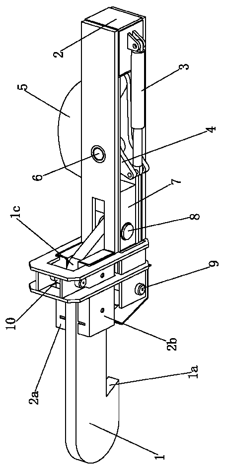
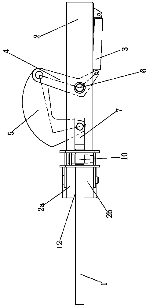
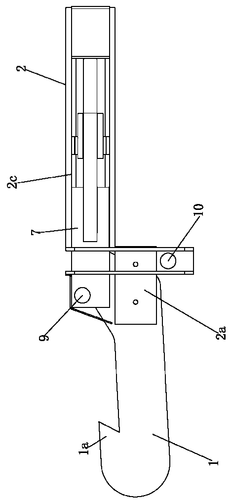
[0019] Such as figure 1 , 3 , Shown in 4 and 5, a connecting rod type hydraulic holding claw device comprises a telescopic oil cylinder 3, a fixed mounting seat 2, a transmission chain, and a movable lock plate 1, and the piston rod of the telescopic oil cylinder 3 is connected with the transmission chain, telescopically The cylinder barrel of the oil cylinder 3 is hinged on the mounting base 2, the locking end of the movable lock plate 1 is provided with a hook 1a for hooking and locking the target body 11, and the telescopic oil cylinder 3 can control the movable lock plate 1 to lock the target body through the transmission chain 11. The transmission chain includes a transmission rod system, a slider 7, and a second rotating shaft 8. The connecting end of the movable lock plate 1 is hinged to one end of the slider 7 through the second rotating shaft 8, and the other end of the slider 7 is connected to the power output of the transmission rod system. The power input end of t...


PUM


Abstract

The invention discloses a connecting rod type hydraulic clamping device in the technical field of mechanical locking devices. The connecting rod type hydraulic clamping device comprises a telescopic cylinder, a fixed mounting seat, a transmission chain and a movable lock plate. When the connecting rod type hydraulic clamping device is in the locking state, a sliding block pulls the movable lock plate so as to enable a second guiding surface to abut against the periphery of a second guiding column, and the movable lock plate rotates under the action of an abutting force of the second guiding column, so that a hook and a target are locked and abutted; and when the connecting rod type hydraulic clamping device is in the unlocking state, the sliding block drives the movable lock plate so as to enable a first guiding surface to abut against the periphery of a first guiding column, and the movable lock plate rotates under the action of an abutting force of the first guiding column, so that the hook is separated from the target. The sliding block in the transmission chain drives the movable lock plate to move, a guiding mechanism formed by the first guiding column and the second guiding column is used for guiding the movement locus of the movable lock plate through abutting, so that the locking and unlocking process of the movable lock plate can be well controlled.

Description

technical field [0001] The invention relates to the technical field of mechanical locking devices, in particular to a hydraulic locking device with a connecting rod type transmission chain. Background technique [0002] Where locking is required, especially when heavy objects (such as dustbins) need to be locked, a hydraulic locking device is required to complete the locking operation. In the past, the hydraulic locking device was set up as follows: it includes an oil cylinder and a lever installed on the piston rod of the oil cylinder. One end of the lever is hinged to the piston rod of the oil cylinder, and the other end of the lever is the locking end. body, the middle part of the lever is inserted with a rotating shaft. During use, the piston rod of the oil cylinder expands and contracts, and the lever is driven to rotate based on its rotating shaft, so that the clip joint at the other end of the lever hooks the target body to complete the locking. [0003] Although th...

Claims


Application Information

Patent Timeline
Patent Type & Authority Patents(China)
IPC IPC(8): B25J15/02
CPCB25J15/0206
Inventor 陈彪
Owner YANGZHOU JINWEI ENVIRONMENTAL PROTECTION TECH CO LTD
Features
  • R&D
  • Intellectual Property
  • Life Sciences
  • Materials
  • Tech Scout
  • Unparalleled Data Quality
  • Higher Quality Content
  • 60% Fewer Hallucinations
Learn More