Trailer card cycloidal tool

A cycloid and jig technology, applied in the field of jigs, can solve problems such as easy lifting of wires, unstable placement, long manual operation time, etc., to reduce manual operation time, quickly place and fix, and improve work efficiency high effect

Inactive Publication Date: 2016-10-26
深圳市国信达科技股份有限公司
View PDF5 Cites 2 Cited by
  • Summary
  • Abstract
  • Description
  • Claims
  • Application Information

AI Technical Summary

Problems solved by technology

[0003] (1) Low efficiency;
[0004] (2) Due to the unstable placement of the wire rod, the wire rod is easy to warp;
[0005] (3) The manual operation takes a long time, resulting in a waste of time
[0006] Therefore, it is necessary to invent a tail clip cycloid jig, which can quickly place and fix the wire rods during injection molding of the power cord tail clips, so as to overcome the low efficiency, unstable placement, and Defects of long working hours

Method used


Image

  • Trailer card cycloidal tool
  • Trailer card cycloidal tool
  • Trailer card cycloidal tool

Examples


Embodiment Construction

[0027] Below with reference to accompanying drawing and in conjunction with embodiment, describe the present invention in detail:

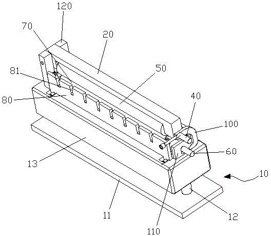
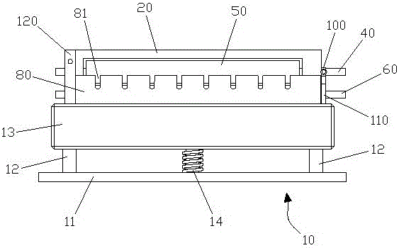
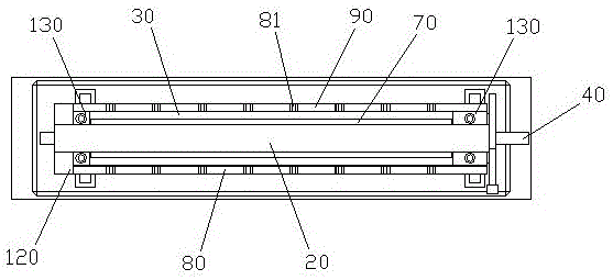
[0028] Such as Figure 1~5 As shown, a tail clip cycloid fixture includes: a base 10, and an upper clamp 20 and a lower clamp 30 arranged on the base 10, the upper clamp 20 is provided with a first groove (not shown), The upper bearing roller 50 is rotated through the first pin 40 in the first groove, and the second groove (not shown) is opened on the lower clamp 30, and the second groove is passed through the second pin 60. A lower bearing roller 70 is provided for rotation, and a limiting space (not shown) is formed between the upper bearing roller 50 and the lower bearing roller 70 to limit the up and down shaking of the wire rod, and the front and rear sides of the lower clamp 30 are respectively provided with front plates 80 and the rear plate 90, the front plate 80 and the rear plate 90 are provided with a number of parallel and one-to-one ...


PUM


Abstract

The invention discloses a trailer card cycloidal tool. The trailer card cycloidal tool comprises a base, and an upper fixture and a lower fixture arranged on the base; a first groove is formed in the upper fixture; an upper bearing roller is rotationally arranged in the first groove through a first bolt; a second groove is formed in the lower fixture; a lower bearing roller is rotationally arranged in the second groove through a second bolt; a limiting space for limiting wires to swing up and down is formed between the upper bearing roller and the lower bearing roller; a front plate and a back plate are respectively arranged on the front and back two sides of the lower fixture; multiple clamping grooves arranged side by side and corresponding one to one are formed in the front plate and the back plate; and the clamping grooves are corresponding to the limiting space for limiting the wires to shake left and right. The trailer card cycloidal tool can quickly place and fix the wires in injection molding of power supply wire trailer cards, can limit the wires to shake up and down and to swing left and right through the upper bearing roller, the lower bearing roller and the clamping grooves, is stable in placement, can once place multiple power supply wires, is high in working efficiency, and effectively shortens the manual operation time.

Description

technical field [0001] The invention relates to a jig, in particular to a cycloid jig for tail clips. Background technique [0002] At present, the tail clips of the power cord are manually placed in a single line during molding and injection molding, and the single line is inserted into the mold line groove. This operation method has the following defects: [0003] (1) Low efficiency; [0004] (2) Due to the unstable placement of the wire rod, the wire rod is easy to warp; [0005] (3) The manual operation takes a long time, resulting in a waste of time. [0006] Therefore, it is necessary to invent a tail clip cycloid jig, which can quickly place and fix the wire rods during injection molding of the power cord tail clips, so as to overcome the low efficiency, unstable placement, and The defect of long working hours. Contents of the invention [0007] The purpose of the present invention is to overcome the deficiencies of the prior art, and to provide a tail clip cycl...

Claims


Application Information

Patent Timeline
Patent Type & Authority Applications(China)
IPC IPC(8): B29C45/14B29C45/32
CPCB29C45/14065B29C45/14639B29C45/32
Inventor 向国东
Owner 深圳市国信达科技股份有限公司
Why Eureka
Try Eureka