Pneumatic tire

一种充气轮胎、轮胎周向的技术,应用在轮胎零部件、轮胎胎面/胎面花纹、运输和包装等方向,达到提高雪上性能、优异雪上性能、提高操纵稳定性的效果

Active Publication Date: 2016-10-26
SUMITOMO RUBBER IND LTD
View PDF5 Cites 17 Cited by
  • Summary
  • Abstract
  • Description
  • Claims
  • Application Information

AI Technical Summary

Problems solved by technology

Such winter tires can exert snow column shearing force through lug grooves when running on snowy roads, but there is room for further improvement in driving on snow compared with tires with block patterns, for example.

Method used


Image

  • Pneumatic tire
  • Pneumatic tire
  • Pneumatic tire

Examples


Embodiment

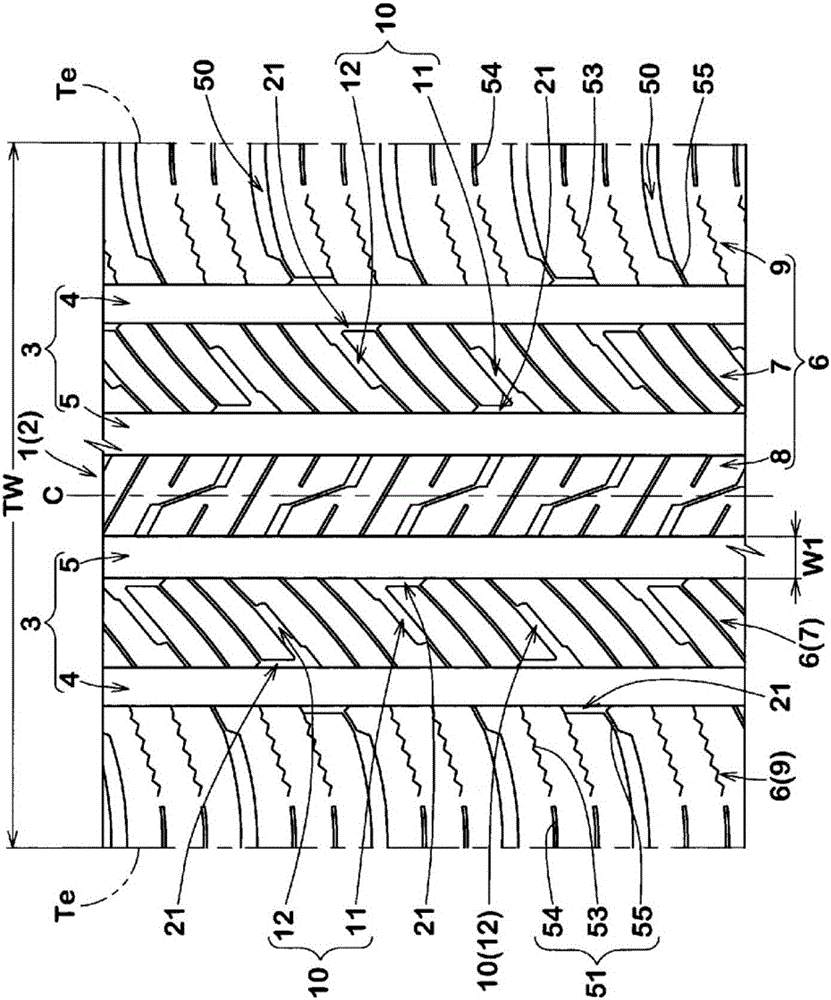
[0108] Prototype has figure 1 Pneumatic tires of the basic pattern size 215 / 60R16. As a comparative example, such as Figure 8 As shown, a pneumatic tire that does not include a chamfered portion was trial-produced. The cornering performance of each test tire on a dry road and an ice-snow road was tested. Common specifications and test methods for each test tire are as follows.

[0109] Mounting rim: 16×6J

[0110] Tire internal pressure: 210KPa

[0111] Test vehicle: Displacement 1800cc, front-wheel drive

[0112] Tire installation position: all wheels

[0113]

[0114] Based on the driver's senses, the driving characteristics related to steering responsiveness, traction, and grip when turning on dry roads and ice and snow roads were evaluated. The results are rated with the comparative example as 100, and a larger numerical value indicates better cornering performance. The test results are shown in Table 1.

[0115] Table 1

[0116]

[0117]

[0118] As a r...


PUM


Abstract

The invention provides a pneumatic tire having excellent driving performance on ice and snow road conditions. The pneumatic tire includes a tread portion (2) being provided with at least one circumferentially and continuously extending main groove (3) and at least one land portion (6) adjacent to the main groove (3). The land portion (6) is provided with a plurality of lug grooves (10) extending from the main groove (3) and terminating within the land portion. A corner portion (20), which is formed between a ground contact surface and a sidewall of the land portion (6) on the side of the main groove, includes a chamfered portion (21) and a non-chamfered portion (22). The chamfered portion (21) includes a first end in communication with the lug grooves (10).

Description

technical field [0001] The present invention relates to a pneumatic tire having excellent running performance on icy and snowy roads. Background technique [0002] Patent Document 1 below describes a winter pneumatic tire in which a main groove and lug grooves extending from the main groove are provided in a tread portion. Such winter tires can exert snow column shearing force through lug grooves when running on snowy roads, but there is room for further improvement in driving on snow compared with tires having blocks or the like, for example. [0003] Patent Document 1: Japanese Patent Laid-Open No. 2010-285035 Contents of the invention [0004] The present invention has been made in view of the above problems, and a main object of the present invention is to provide a pneumatic tire having excellent running performance on icy and snowy roads based on the provision of lug grooves and chamfered portions on land portions. [0005] In the pneumatic tire of the present inve...

Claims


Application Information

Patent Timeline
Patent Type & Authority Applications(China)
IPC IPC(8): B60C11/12B60C11/03
CPCB60C11/0309B60C11/1272B60C11/0311B60C11/0306B60C11/1392B60C11/12B60C2011/0341B60C2011/0365B60C2011/0372B60C2011/133B60C11/0332B60C11/1307B60C2011/0334B60C2011/0376B60C2011/0386
Inventor 山冈宏
Owner SUMITOMO RUBBER IND LTD
Why Eureka
Try Eureka