Partition automatic feeding device

An automatic feeding and spacer technology, applied in transportation and packaging, conveyor objects, conveyors, etc., can solve the problems of a large number of spacer trays, high labor costs, and high production costs, and reduce manual placement of spacers. The effect of reducing the process and staffing requirements and reducing the production cost

Active Publication Date: 2019-02-19
ZHEJIANG SUNNY OPTICAL CO LTD
View PDF8 Cites 0 Cited by
  • Summary
  • Abstract
  • Description
  • Claims
  • Application Information

AI Technical Summary

Problems solved by technology

[0002] The spacer is an essential part of the lens, especially in the mobile phone lens, it can reduce stray light, and can effectively improve the performance and quality of the mobile phone lens. In the prior art, there are usually two supply methods for the spacer: One is to use the manual method in the whole process; the other is to manually place it on the spacer tray first, and then complete the follow-up process by the robot. However, the above two methods have the disadvantage of low worker operation efficiency. Manual operation is easy to damage the spacer and other parts of the mobile phone lens; and because a finished lens needs to have multiple spacers of different specifications, the operator needs to configure a huge workload, high labor costs, and poor accuracy, not only resulting in high production costs, but also Moreover, quality accidents are caused due to manual misoperation, and the spacers are placed on the spacer tray. Due to the large number of spacers and the large number of spacers, the number of spacer trays required is huge, which increases the production cost.

Method used


Image

  • Partition automatic feeding device
  • Partition automatic feeding device
  • Partition automatic feeding device

Examples


Embodiment Construction

[0020] The specific embodiments of the present invention will be further described in detail below in conjunction with the accompanying drawings.

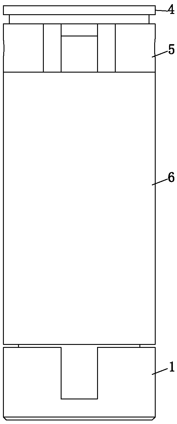
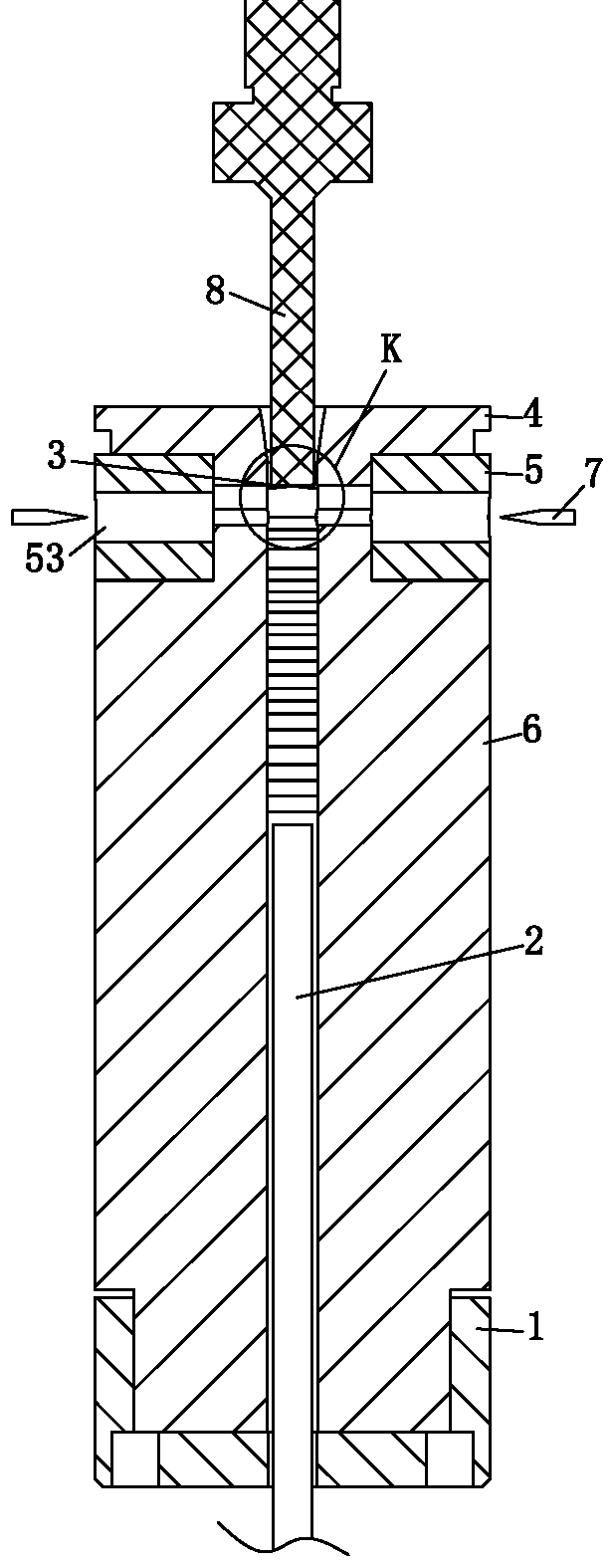
[0021] Such as Figure 1-Figure 7 As shown, the spacer automatic feeding device involved in the present invention includes a bucket base 1, a thimble 2 and a thimble moving module, the bucket base 1 is provided with a through hole 11 in the bucket base, and the lower end of the thimble 2 moves with the thimble The modules are connected, and also include a separation plate 4 and a material barrel 6, the separation plate 4 is provided with a separation plate outlet 42, the material barrel 6 is axially provided with a spacer material storage hole 61, and the spacer 3 is stored in the spacer In the material storage hole 61, the separation plate 4 is arranged above the material barrel 6, and the material barrel 6 is arranged on the material barrel base 1. Coincidentally, the thimble 2 is inserted into the spacer material storage hole 6...


PUM


Abstract

The invention relates to an automatic feeding device for a spacer. The automatic feeding device comprises a charging basket base, an ejector pin and an ejector pin moving module, and further comprises a separation plate and a charging basket. A separation plate outlet is formed in the separation plate. A spacer storage hole is formed in the charging basket in the axial direction. The spacer is stored in the spacer storage hole. The center lines of a charging basket base through hole, the separation plate outlet and the spacer storage hole coincide with one another. The ejector pin penetrates through the charging basket base through hole to be inserted in the spacer storage hole of the charging basket, and the upper end of the ejector pin is propped against the spacer. Through the technical scheme, manual placing can be replaced, and the defect of a conventional feeding process is eliminated; thousands of spacers can be stored at one time, automatic feeding can be realized, misoperation that two or more spacers are sucked synchronously can be effectively prevented, a spacer tray and a process of placing the spacers manually are omitted, the using cost of a tool jig is reduced, personnel allocation requirements are reduced greatly, the production efficiency is improved effectively, and the production and manufacturing cost is reduced.

Description

technical field [0001] The invention relates to a feeding device, in particular to an automatic feeding device for partitions. Background technique [0002] The spacer is an essential part of the lens, especially in the mobile phone lens, it can reduce stray light, and can effectively improve the performance and quality of the mobile phone lens. In the prior art, there are usually two supply methods for the spacer: One is to use the manual method in the whole process; the other is to manually place it on the spacer tray first, and then complete the follow-up process by the robot. However, the above two methods have the disadvantage of low worker operation efficiency. Manual operation is easy to damage the spacer and other parts of the mobile phone lens; and because a finished lens needs to have multiple spacers of different specifications, the operator needs to configure a huge workload, high labor costs, and poor accuracy, not only resulting in high production costs, but al...

Claims


Application Information

Patent Timeline
Patent Type & Authority Patents(China)
IPC IPC(8): B65G47/06
CPCB65G47/06B65G2201/022
Inventor 张海挺叶小伟沈科良
Owner ZHEJIANG SUNNY OPTICAL CO LTD
Why Eureka
Try Eureka