Lifting tube and handling device

A hose and climbing angle technology, applied in the field of operating equipment, can solve problems such as cannot be easily reduced, and achieve the effect of small local stress and high shear motion

Inactive Publication Date: 2016-10-26
J SCHMALZ GMBH
View PDF6 Cites 4 Cited by
  • Summary
  • Abstract
  • Description
  • Claims
  • Application Information

AI Technical Summary

Problems solved by technology

The contraction ratio of such a lifting hose, i.e. the ratio of the axial length in the contracted configuration to the length in the extend

Method used


Image

  • Lifting tube and handling device
  • Lifting tube and handling device
  • Lifting tube and handling device

Examples


Embodiment Construction

[0032] In the figures and in the following description, the same reference symbols are used in each case for identical or mutually corresponding features.

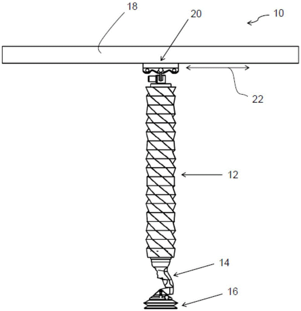
[0033] figure 1 An overview of a hose lifter 10 is shown with a lifting hose 12 described below, wherein the end of the lifting hose 12 is coupled via a handling device 14 to a suction gripping device 16 . The lifting hose 12 is connected with its end opposite the suction gripping device 16 to the support body 18 , in particular the suspension point 20 of the lifting hose 12 is displaceable in a transverse direction 22 .

[0034] Objects to be gripped (not shown) can be sucked by means of the vacuum gripping device 16 . By suitable actuation of the operating device 14 , the lifting hose 12 can be shortened by applying a negative pressure to its hose interior (see below) and thus the grasped object can be lifted.

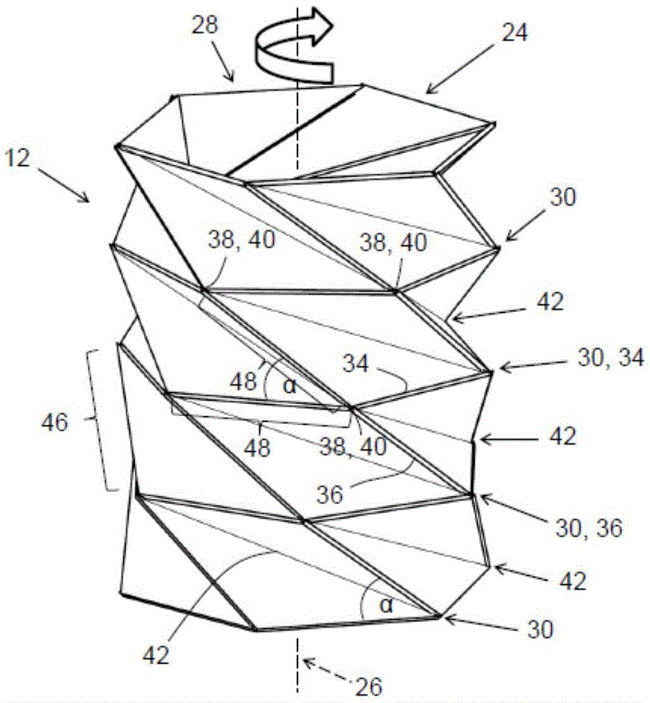
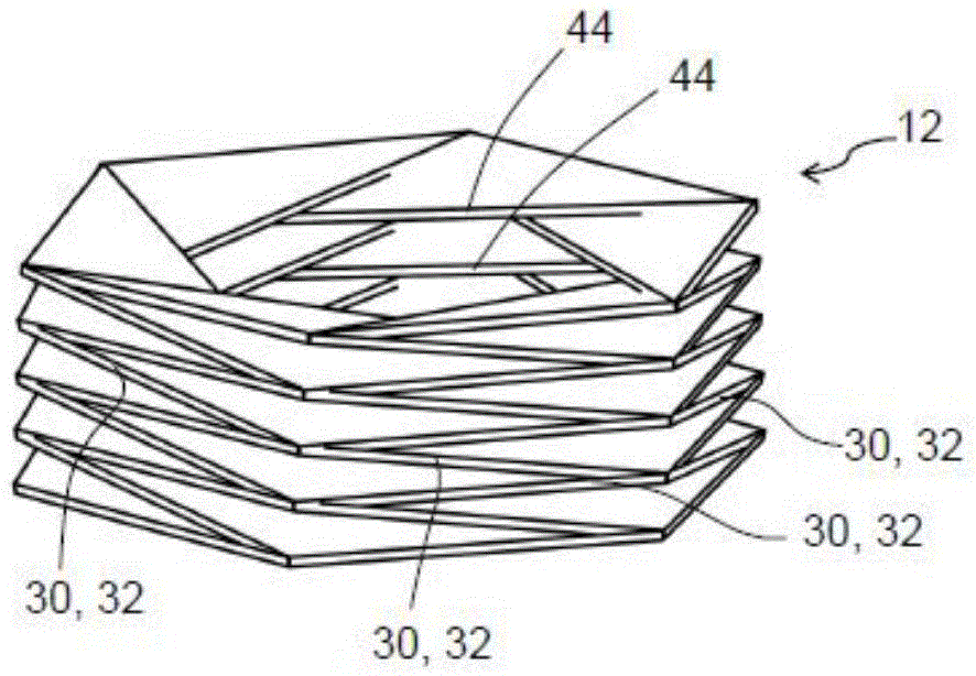
[0035] Figure 2 to Figure 5 Different views and different configurations of sections of the lifting hose ...


PUM


Abstract

The invention concerns a lifting tube as well as a vacuum lifting device with such a lifting tube. The lifting tube has a tube wall extending about a lengthwise axis and enclosing a tube interior, while the lifting tube can be reversibly deformed along its lengthwise axis into an elongated configuration and, with reduction of the tube interior, a contracted configuration. The tube wall has a plurality of outer crease lines, along which the tube wall can buckle to produce the contracted configuration, while the outer crease lines run obliquely to each other so that, when deformed into the contracted configuration, the tube wall experiences a torsion about the lengthwise axis in some sections.

Description

technical field [0001] The invention relates to a lifting hose according to the preamble of claim 1 and to an operating device according to the preamble of claim 15 . Background technique [0002] Hoisting hoses of this type are used, for example, in hose hoists. In this case, the lifting of the gripped object is assisted by shortening the lifting hose caused by the negative pressure. However, other applications such as pneumatic actuators are also conceivable for lifting hoses. In this case, the elongation of the lifting hose by the negative pressure can exert a force on the object, for example in order to lift or move a load. [0003] Hose lifters with lifting hoses of this type are described, for example, in WO 2005 / 110907 A1 or US Pat. No. 4,413,853. The lifting hose has a bellows-shaped configuration with circumferential annular folds formed alternately as inner and outer folds along the axial extension, or with a longitudinal axis with a spiral shape surrounding the...

Claims


Application Information

Patent Timeline
IPC IPC(8): B66C1/02
CPCB66C1/0293B66C1/0212B25J15/0616
Inventor 乔纳斯·马斯特乔纳森·科勒
Owner J SCHMALZ GMBH
Why Eureka
Try Eureka