steel support structure

A technology for supporting structures and steel structures, applied in pillars, building structures, buildings, etc., can solve the problems of inability to set up platforms, inconsistent appearance, inability to set beams, etc., and achieve simple structure, neat and uniform appearance, and enhanced bearing capacity. Effect

Active Publication Date: 2019-03-19
李新华
View PDF7 Cites 0 Cited by
  • Summary
  • Abstract
  • Description
  • Claims
  • Application Information

AI Technical Summary

Problems solved by technology

This kind of structural setting brings many restrictions to the implementation of the steel structure. First, the appearance is complicated. Due to structural limitations, the length of the beam can only be set to the length between the two columns, and the ends of the beam beyond the length limit will not be able to be installed on the male legs of the two columns
The third is to limit the structure of steel structure products. For example, it is necessary to set up a lifting platform at a certain height. Since the ends of the beams of the existing structure need to be supported on the columns, if only one end has a column, the beam cannot be installed. , it is not possible to set the platform

Method used


Image

  • steel support structure
  • steel support structure
  • steel support structure

Examples


Embodiment 1

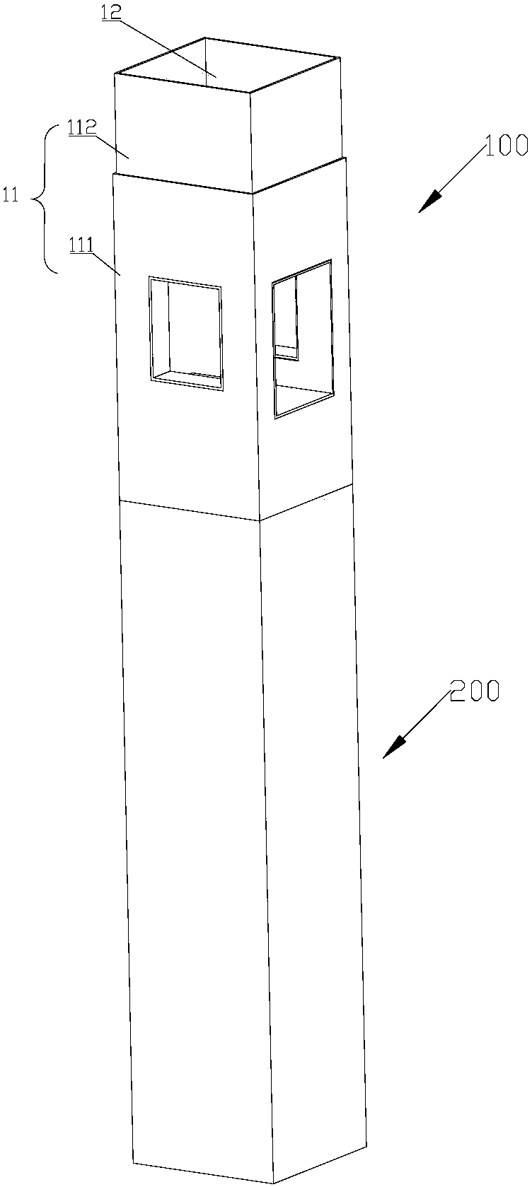
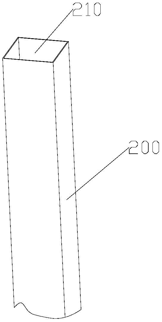
[0057] Such as figure 1 , figure 2 As shown, the steel structure supporting structure includes a column 200 and a corbel structure 100 . The post 200 is a tubular structure that includes a post lumen 210 .

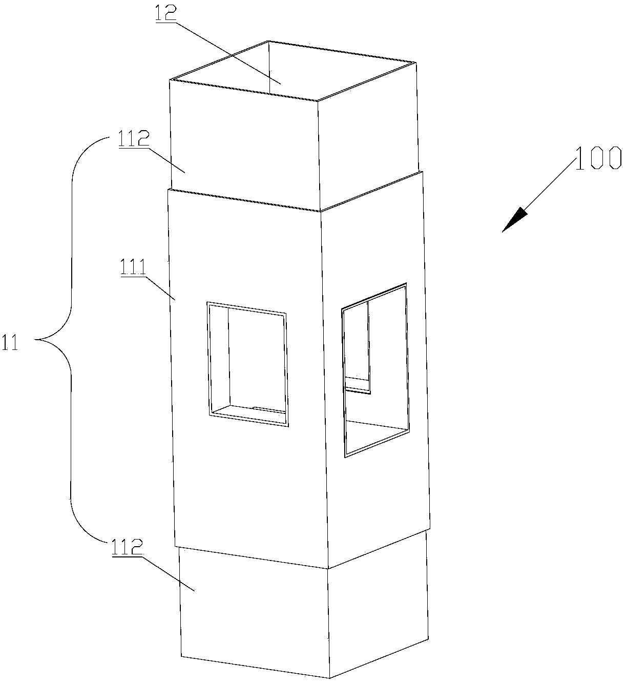
[0058] Such as image 3 , Figure 4 , Figure 5 with Image 6 As shown, a steel structure corbel 100 includes a sleeve 10 and a connecting piece 20 . The cannula 10 has a cannula wall 11 which encloses a cannula lumen 12 . The tube wall of the sleeve includes a sleeve body 111 and an insertion tube 112 . Two ends of the sleeve main body 111 are respectively provided with a plug-in tube 112 . The insertion tube 112 and the casing main body 111 are integrally structured. The external dimensions of the socket tube 112 are smaller than the sleeve main body 111 . The insertion tube 112 is inserted into the column lumen 210 . The outer wall of the casing main body 111 is aligned with the outer wall of the column 200 . The sleeve tube wall 11 is provided with a first...

Embodiment 2

[0067] Such as Figure 8 As shown, the corbel structure in this embodiment is different from that in Embodiment 1. The corbel structure 100 includes a casing 10 and a connecting piece 20 . Sleeve 10 structure such as image 3 shown. The casing 10 has a casing wall 11, the casing wall 11 encloses a casing lumen 12, and the casing wall 11 is provided with a first through hole 13 penetrating through the casing wall 11 . The shape of the casing wall 11 and the shape of the casing lumen 12 can be quadrangular or circular, and can also be selected as other shapes according to actual needs. The quadrilateral can be a rectangle, a square or other available shapes. In the example shown, the cannula wall 11 is rectangular and the cannula lumen 12 is also rectangular. The position and number of the first through holes 13 can be selected according to actual needs. In this embodiment, four first through holes 13 are respectively opened on four surfaces of the rectangular casing wall...

Embodiment 3

[0074] Figure 11 The internal structure of the sleeve lumen in this embodiment is shown. The difference between this embodiment and Embodiment 1 is that the structure of the corbel is different. Such as Figure 11 As shown, the steel structure corbel includes a casing 10 and a connecting piece 20 . Sleeve 10 structure such as figure 1 shown. The cannula 10 has a cannula wall 11 which encloses a cannula lumen 12 . The sleeve tube wall 11 is provided with a first through hole 13 penetrating through the sleeve tube wall 11 . The shape of the casing wall 11 and the shape of the casing lumen 12 can be quadrangular or circular, and can also be selected as other shapes according to actual needs. The quadrilateral can be a rectangle, a square or other available shapes. In the example shown, the cannula wall 11 is rectangular and the cannula lumen 12 is also rectangular. The position and number of the first through holes 13 can be selected according to actual needs. In this e...


PUM


Abstract

The invention discloses a steel support structure. The steel support structure is characterized in that the steel support structure comprises a column and a bracket structure; the column has a column cavity; the bracket structure comprises a casing pipe; the casing pipe has a casing pipe wall which is enclosed to form a casing pipe cavity; the casing pipe wall is provided with a first through hole penetrating the casing pipe wall; and the first through hole is communicated with the casing pipe cavity, and the casing pipe wall is connected with the column. The steel support structure can overcome problems in continuation of beams, fixation of structures and strength of nodes of steel structures and ingeniously carrying out welding in virtue of concrete pouring grooves on beam tops; so problems in construction of steel structures are thoroughly overcomes.

Description

technical field [0001] In particular, the invention relates to a steel structural support structure. Background technique [0002] Steel structures are widely used in modern house construction. In a steel structure house, its structure consists of columns and beams. Uprights support beams. According to different load-bearing capacity requirements, beams are divided into main beams and secondary beams. The beam is supported by columns. In the prior art, the connection between the column and the beam is realized by using a male corbel structure. The positive corbel is arranged on the outer surface of the column. The ends of the beams are connected to the male corbels. This kind of structural setting brings many restrictions to the implementation of the steel structure. First, the appearance is complicated. Due to structural restrictions, the length of the beam can only be set to the length between the two columns, and the two ends of the beam beyond the length limit can...

Claims


Application Information

Patent Timeline
Patent Type & Authority Patents(China)
IPC IPC(8): E04C3/32E04B1/58
CPCE04B1/58E04C3/32
Inventor 李新华
Owner 李新华
Why Eureka
Try Eureka