Pump turning direction hydraulically-started reversible water turbine and work method thereof

A water turbine and hydraulic technology, applied in hydroelectric power generation, engine components, machines/engines, etc., can solve the problems of expensive equipment, complicated operation, and large space occupied by equipment, and achieve the effect of preventing flyaway and simple operation

Active Publication Date: 2016-10-26
浙江临海浙富电机有限公司
View PDF5 Cites 4 Cited by
  • Summary
  • Abstract
  • Description
  • Claims
  • Application Information

AI Technical Summary

Problems solved by technology

[0003] In order to overcome the disadvantages of complicated start-up operation, expensive equipment, and large space occupied by the equipment in the pump rotation condition of the current medium and large reversible units, the present invention provides a reversible water turbine that can adapt to the rapid start of the pump rotation condition and its working method. Use water energy to start, control the flow of water entering the unit by operating the needle valve, adjust the speed of the unit, and connect to the grid at the same time when the synchronous speed is reached, and enter the pump rotation mode to operate. The operation is simple and fast, and there is no impact on the grid system and no harmonics. No need to increase equipment space separately, saving investment and reducing the risk of startup failure

Method used


Image

  • Pump turning direction hydraulically-started reversible water turbine and work method thereof
  • Pump turning direction hydraulically-started reversible water turbine and work method thereof

Examples


Embodiment Construction

[0025] The present invention will be described in further detail below in conjunction with the accompanying drawings, but it is not intended to limit the protection scope of the present invention.

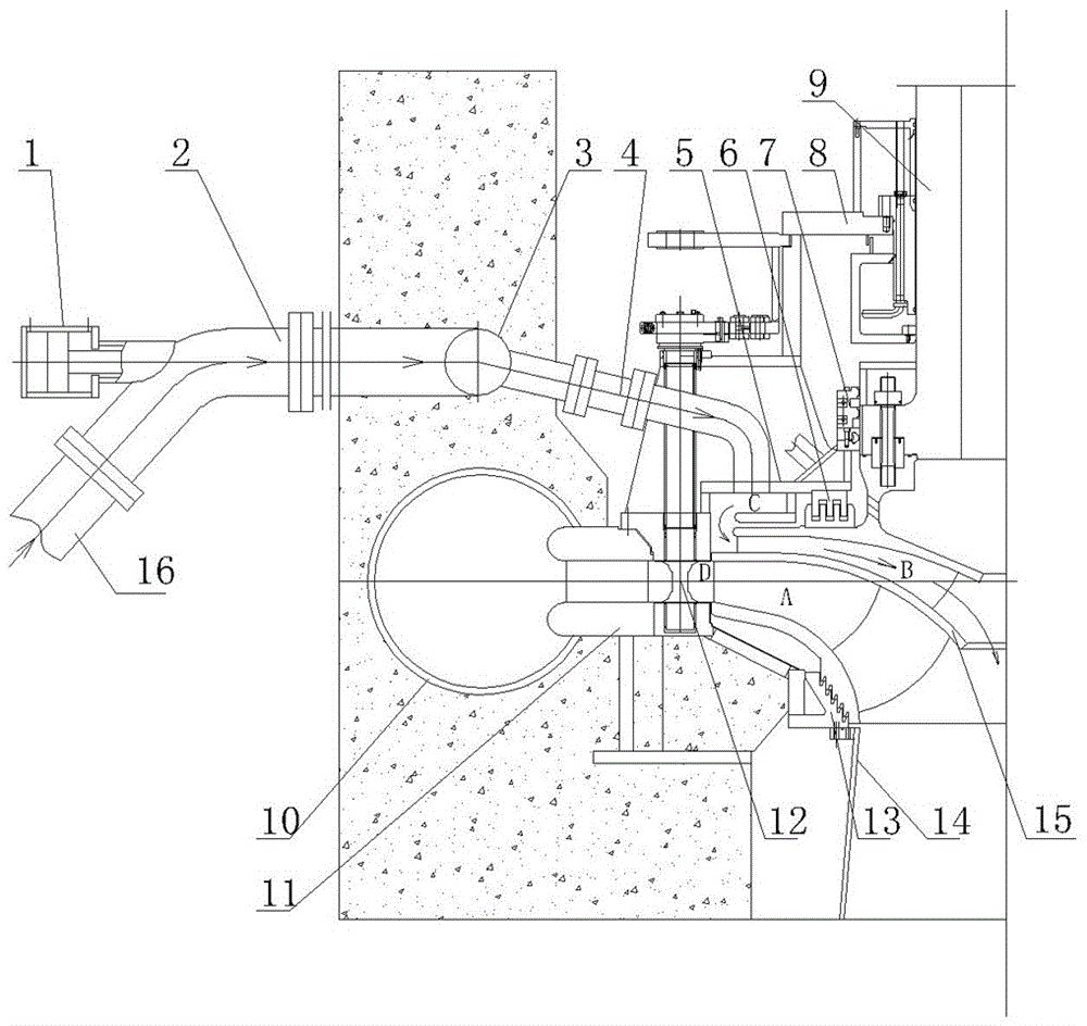
[0026] Such as figure 1 As shown in the figure, a reversible water turbine with hydraulic start in the direction of rotation of the pump includes a needle valve operating device 1, a needle valve 2, a ring pipe 3, an expansion joint 4, a top cover 5, an upper fixed leak-proof ring 6, a main shaft seal 7, water Guide bearing 8, main shaft 9, volute 10, seat ring 11, movable guide vane 12, lower fixed leak-proof ring 13, draft tube 14, runner 15.

[0027] The diversion pipe before the needle valve 2 is connected to the pressure steel pipe 16 behind the water inlet valve of the unit, the water pipe behind the needle valve 2 is connected to the ring pipe 3, the needle valve 2 is opened and closed by the needle valve operating device, and the ring pipe 3 is connected to multiple Two te...


PUM


Abstract

The invention discloses a pump turning direction hydraulically-started reversible water turbine. The pump turning direction hydraulically-started reversible water turbine comprises a ring pipe, telescopic joints, a top cover, a main shaft, a seat ring, a movable guide vane, a tail water pipe and a runner. The ring pipe is connected with a needle valve operation device. The top cover is provided with a water guiding chamber. The runner is provided with a main runner channel and an auxiliary runner channel. The water inlet end of a needle valve communicates with a pressure steel pipe behind a unit water inlet valve. The water outlet end of the needle valve is connected with the ring pipe. The ring pipe is connected with the multiple telescopic joints. The telescopic joints communicate with the water guiding chamber on the top cover. An outlet of the water guiding chamber corresponds to an opening in the outer edge of the auxiliary runner channel. An opening in the inner side of the auxiliary runner channel communicates with the tail water pipe. The inner side of the seat ring communicates with the movable guide vane. The inner side of the movable guide vane corresponds to an opening in the outer edge of the main runner channel. An opening in the inner side of the main runner channel communicates with the tail water pipe. The main shaft is connected with the runner to transmit torque. Pump turning direction starting does not impact on a power grid and does not generate harmonic sources, operation is easy, extra space is not occupied, components prone to damage do not exist, and safety and reliability are achieved.

Description

technical field [0001] The invention relates to a water turbine, in particular to a reversible water turbine with pump rotation and hydraulic start and a working method thereof. Background technique [0002] At present, for medium and large mixed-flow reversible hydro-generator units, the start-up method of the pump rotation condition directly powered by the grid to the motor will cause a great impact on the grid. Usually, the unit needs to be rotated to the synchronous speed, and then connected to the grid at the same time. This requires expensive starting equipment, complicated operating procedures, and additional equipment takes up a lot of space, such as the commonly used inverter starting and back-to-back starting methods. When the frequency converter is used, it will generate harmonics, which will become the harmonic source of the power grid system, and at the same time cause the voltage of the plant power system to be deformed; back-to-back start-up requires special e...

Claims


Application Information

Patent Timeline
Patent Type & Authority Applications(China)
IPC IPC(8): F03B3/02F03B3/12F03B11/00F03B15/00F03B15/04
CPCF03B3/02F03B3/125F03B11/00F03B11/004F03B15/005F03B15/04Y02E10/20
Inventor 周庆大
Owner 浙江临海浙富电机有限公司
Why Eureka
Try Eureka