
Multi-float-rod wave power generation device

A power generation device, wave energy technology, applied in ocean energy power generation, engine functions, engine components, etc., can solve the problem that low-power wave energy power generation cannot be well applied, and cannot adapt to the actual situation of changing sea conditions, wave energy power generation device Can not be applied well, to achieve the effect of fully absorbing wave energy, fast response, and enhancing self-sustaining ability

Inactive Publication Date: 2016-10-26
NORTHWESTERN POLYTECHNICAL UNIV
View PDF7 Cites 14 Cited by
  • Summary
  • Abstract
  • Description
  • Claims
  • Application Information

AI Technical Summary

Problems solved by technology

[0004] In the invention with the publication number of 102094746A, a single pendulum type wave energy power generation system is disclosed. This device uses the mechanical energy generated by the weight inside the floating body to generate electricity when it swings with the waves, but the natural frequency of the weight swing is fixed. value, unable to adapt to the actual situation of changing sea conditions
When the natural frequency of the pendulum does not match the frequency of the ocean waves, power generation is inefficient
[0005] Due to the above reasons, existing wave energy generating devices cannot be well applied in practice, especially in the field of low-power wave energy generation.

Method used


Image

  • Multi-float-rod wave power generation device
  • Multi-float-rod wave power generation device
  • Multi-float-rod wave power generation device

Examples


Embodiment Construction

[0021] The present invention will be further described below in conjunction with the accompanying drawings and embodiments, and the present invention includes but not limited to the following embodiments.

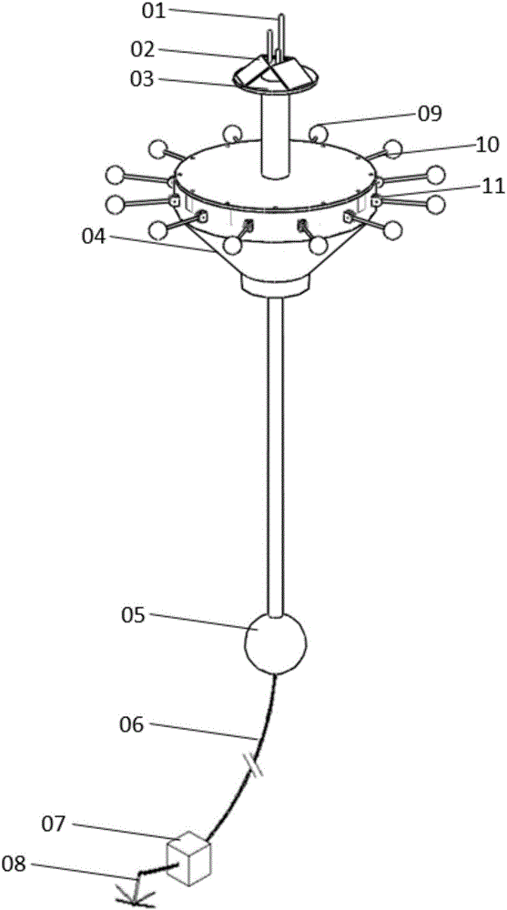
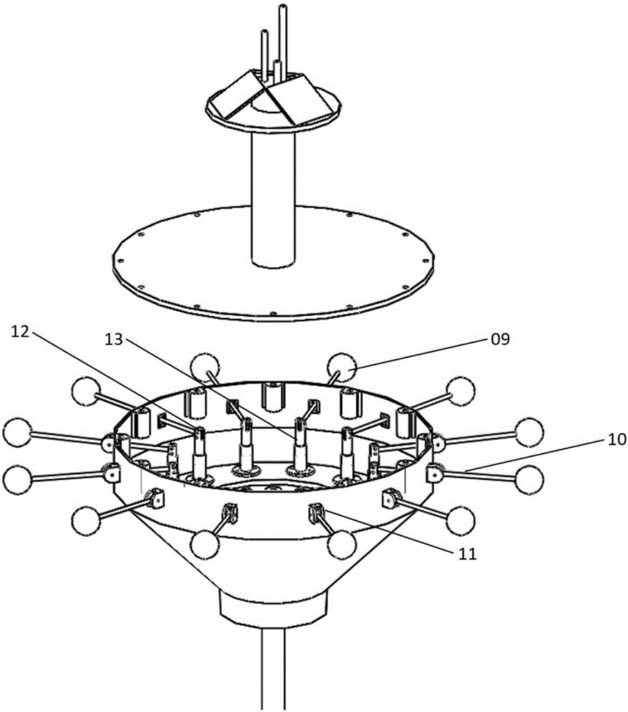
[0022] The multi-floor wave energy generating device provided by the present invention includes a buoy main body, an anchoring system, a wave energy capture system, a hydraulic transmission system and a power generation system. The main body of the buoy floats on the sea surface and is moored by the mooring system. The wave energy capture system is distributed around the main body of the buoy, and the hydraulic transmission system and power generation system are arranged in the main body of the buoy.

[0023] The buoy body includes an instrument platform-a buoy shell-a gravity ball. The instrument platform is located on the top of the main body of the buoy. The instrument platform is equipped with solar panels and instrument racks. Anemometers, navigation lights and communi...


PUM


Abstract

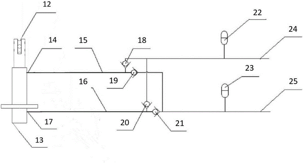
The invention provides a multi-float-rod wave power generation device. The multi-float-rod wave power generation device comprises a buoy shell, float rods, a plurality of hydraulic cylinders, a hydraulic motor and a power generator; the buoy shell is a closed hollow cavity, the hydraulic cylinders are installed inside the buoy shell, and a sliding wheel is arranged at the top end of a piston rod of each hydraulic cylinder; one ends of the float rods with the same number as the hydraulic cylinders are connected to floating balls, and the other ends of the float rods penetrate through side walls of the buoy shell and are connected to the sliding wheels; the float rods are hinged to the side walls of the buoy shell, and the piston rods are driven to do reciprocating motion under the effect of waves; the hydraulic cylinders are connected to energy accumulators through conveying pipes with check valves, and therefore hydraulic oil can be circulated among the hydraulic cylinders, the high-pressure energy accumulator, the hydraulic motor, an oil tank and the low-pressure energy accumulator in a one-way mode; and the hydraulic motor drives the power generator to work. The multi-float-rod wave power generation device is high in response speed, can adapt to sea conditions of different frequency, is suitable for the field of small-scale power generation, is flexible to apply, is free of influence of incoming wave directions, can absorb the wave energy fully and has higher efficiency.

Description

technical field [0001] The invention relates to the field of new energy equipment, in particular to a wave energy generating device. Background technique [0002] As the global energy crisis intensifies, the development and utilization of various new forms of renewable energy has become the focus of increasing attention by countries all over the world. Ocean energy represented by wave energy has the characteristics of huge reserves, clean and renewable, and is an alternative energy form with great development potential. Among them, wave energy appears in the form of mechanical energy, which is the highest-grade ocean energy. The world's available wave energy is about 2 billion KW, and our country is about 100 million KW. All major oceanic countries in the world attach great importance to the research and utilization of wave energy, and have successively invented wave energy conversion devices such as oscillating water column, pendulum, raft, shrinking channel, oscillating b...

Claims


Application Information

Patent Timeline
Patent Type & Authority Applications(China)
IPC IPC(8): F03B13/14
CPCF03B13/14F05B2260/406Y02E10/30
Inventor 王冠华毛昭勇王驰宇包亨达姬文忠王媖李波
Owner NORTHWESTERN POLYTECHNICAL UNIV
Learn More