
compressor

A compressor and crankshaft technology, applied in the field of compressors, can solve the problems of reducing the strength of the crankshaft 1 and failing to clean the root

Active Publication Date: 2018-09-07
ZHUHAI LANDA COMPRESSOR +1
View PDF9 Cites 0 Cited by
  • Summary
  • Abstract
  • Description
  • Claims
  • Application Information

AI Technical Summary

Problems solved by technology

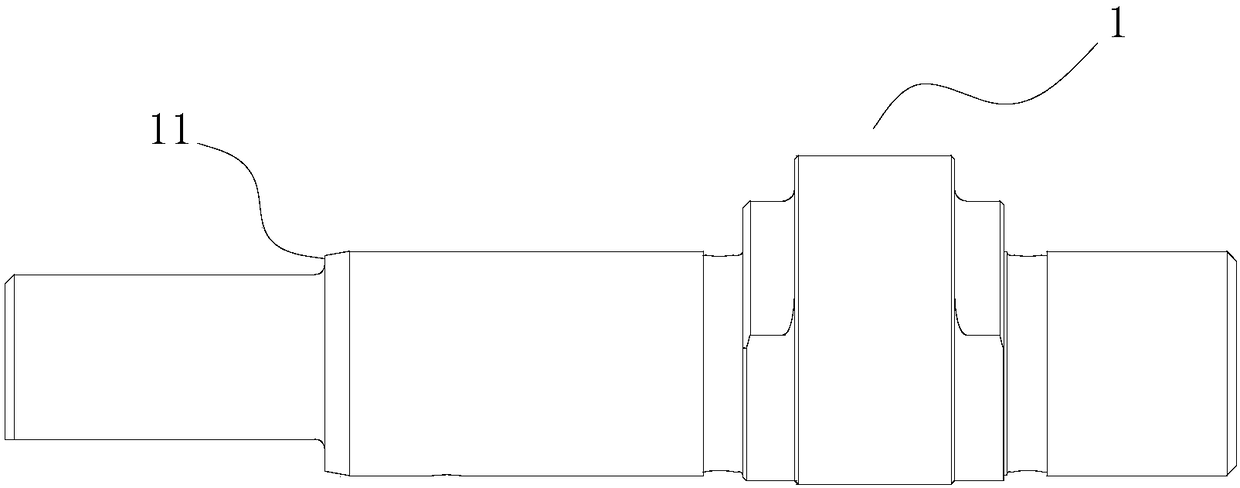
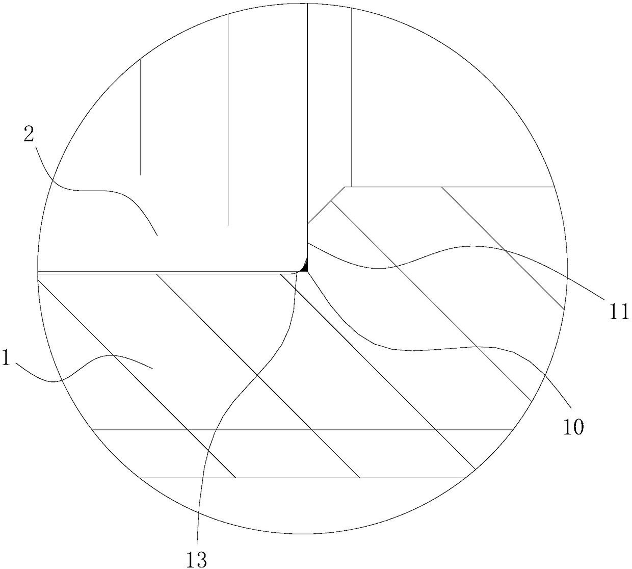
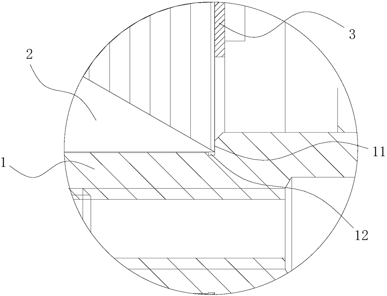
[0004] In the case where a transition fillet is formed at the connection between the arc and the straight line of the rotor core, such as figure 1 and figure 2 As shown, if a transition angle 13 is provided at the root of the support surface 11 at the trimming position of the long axis of the crankshaft 1, an interference area 10 will be generated between the transition angle 13 and the rotor core 2; figure 1 and image 3 As shown, the root cleaning groove 12 can be set at the root of the support surface 11 at the trimming position of the long axis of the crankshaft 1 to avoid the transition fillet of the rotor core, but if the depth of the root cleaning groove 12 is too large, the strength and depth of the crankshaft 1 will be reduced. Too small to achieve the purpose of clearing the root (avoidance)

Method used


Image

  • compressor
  • compressor
  • compressor

Examples


Embodiment 1

[0029] The preferred embodiment discloses a compressor. Such as Figure 4 and Figure 5 As shown, the compressor includes a crankshaft 1, a rotor core 2 and a sheet-shaped baffle 3. One side of the baffle 3 is attached to the support surface 11 at the trimming position of the long axis of the crankshaft 1, and the other side is attached to the rotor iron core. Core 2 on.

[0030] A baffle 3 is set between the support surface 11 at the long axis trimming position of the crankshaft 1 and the rotor core 2, which solves the problem of the transition between the circular arc and the straight line connection of the rotor core 2 and the crankshaft 1 in the existing structure. If the problem of interference occurs, it is ensured that the rotor core 2 will not tilt after assembly and will not affect the coaxiality of the stator-rotor.

[0031] The specific structure of the baffle plate 3 is not limited, as long as it can separate the supporting surface 11 of the long axis trimming p...

Embodiment 2

[0040] This preferred embodiment discloses a micro compressor. The micro-compressor includes a crankshaft, a rotor iron core and a sheet-shaped baffle. One side of the baffle is attached to the support surface of the long axis trimming position of the crankshaft, and the other side is attached to the rotor iron core. It solves the problem of interference between the transition fillet and the crankshaft at the connection between the circular arc and the straight line of the rotor iron core in the existing structure, and ensures that the rotor iron core will not tilt after assembly and will not affect the coaxiality of the stator-rotor.


PUM


Abstract

The invention discloses a compressor, and belongs to the technical field of compressing devices. The compressor is designed for solving the problems that according to an existing device, crankshafts intervene, and are low in strength. The compressor comprises a crankshaft and a rotor iron core and further comprises a piece-shaped baffle; one face of the baffle is attached to the supporting face of the long-axis trimming position of the crankshaft, the other face of the baffle is attached to the rotor iron core, the baffle is of an annular structure, an inner ring of the baffle comprises an arc line segment and a straight line segment, and the arc line segment and the straight line segment are connected to form a close structure; the crankshaft is arranged in the inner ring of the baffle in a penetrating manner; and the compressor solves the intervening problem of the crankshaft and the transition corner at the connecting position of the circular arc and the straight line of the rotor iron core in an existing structure, it is ensured that after being assembled, the rotor iron core cannot incline, and coaxiality of a stator-rotor cannot be affected; and a back chipping groove does not need to be formed in the root of the supporting face of the long-axis trimming position of the crankshaft, and it is ensured that the crankshaft has the enough strength.

Description

technical field [0001] The invention relates to the technical field of compression devices, in particular to a compressor. Background technique [0002] Micro compressor refers to a refrigeration compressor with a cooling capacity of less than 1KW, which is small in size, light in weight, strong in durability, low in noise, and low in energy consumption. [0003] The existing micro-compressor includes a rotor iron core and a crankshaft, and the rotor iron core is in contact with the support surface at the trimming position of the long axis of the crankshaft. Theoretically speaking, the circular arc and straight line of the inner ring of the rotor core are directly connected, but in fact, as the high die punch wears out, the connection between the circular arc and the straight line of the rotor core has a transition fillet. [0004] In the case where a transition fillet is formed at the connection between the arc and the straight line of the rotor core, such as figure 1 and...

Claims


Application Information

Patent Timeline
Patent Type & Authority Patents(China)
IPC IPC(8): F04B39/00
CPCF04B39/00F04B39/0094
Inventor 刘清辉林婵琼袁亮贵侯岩
Owner ZHUHAI LANDA COMPRESSOR
Learn More