Supercharge Your Innovation With Domain-Expert AI Agents!

Sealing structure for vapor chamber

A vapor chamber and sealing technology, which is applied to lighting and heating equipment, indirect heat exchangers, etc., can solve the problems of complex manufacturing process, easy damage and loss of internal vacuum state, and difficulty in maintaining for a long time, so as to achieve no solder pollution and conform to The effect of environmental appeal and simplification of manufacturing process

Inactive Publication Date: 2016-10-26
SUZHOU FORCECON ELECTRIC
View PDF1 Cites 1 Cited by
  • Summary
  • Abstract
  • Description
  • Claims
  • Application Information

AI Technical Summary

Problems solved by technology

[0003] However, in the actual application experience, it is found that there are still some problems and disadvantages in the above-mentioned structure and molding method of the existing chamber, because the gap is usually formed around the upper cover plate when stamping out the shape of the three-dimensional casing. It is formed by punching out a half-tube shape, and after being stacked and combined with the lower cover plate, a gap with an opening facing the side is formed. In addition to the shortcomings of the good moving line, the setting of the gap will affect the ideal shape of the upper cover and the lower cover that can be combined and closed in a ring, causing the internal vacuum state to be easily damaged and lost and difficult to maintain for a long time, and because The gap must be soldered and closed with solder after the steps of vacuuming and liquid injection are completed, which makes the manufacturing process somewhat complicated, and the use of the solder is more polluting and not environmentally friendly.

Method used


Image

  • Sealing structure for vapor chamber
  • Sealing structure for vapor chamber
  • Sealing structure for vapor chamber

Examples


Embodiment

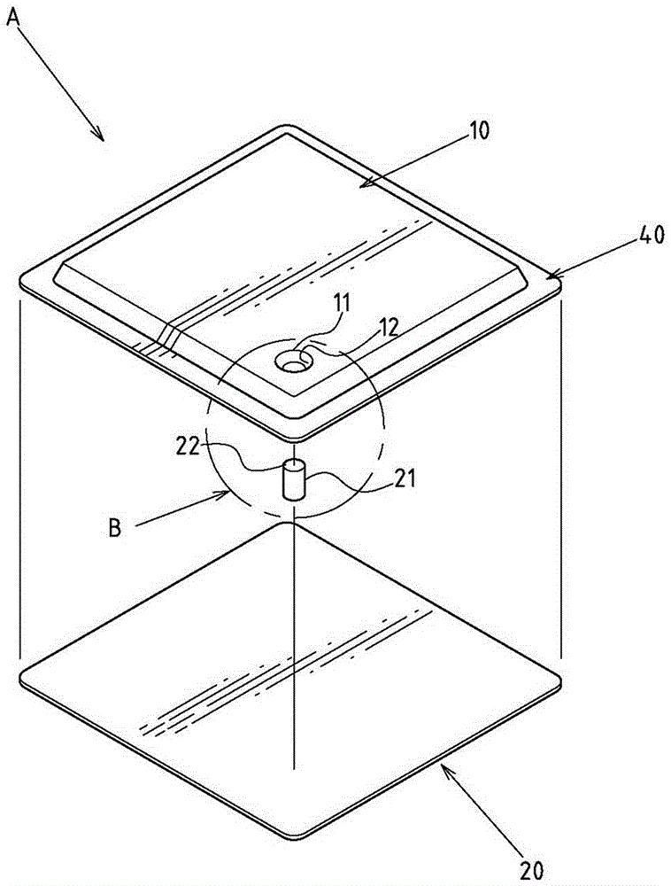
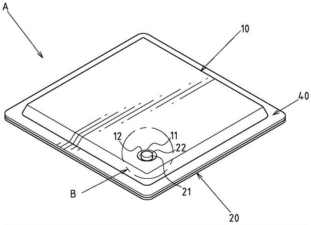
[0029] Example: see Figure 1~4 As shown, it is a preferred embodiment of the sealing structure of the vapor chamber of the present invention, but these embodiments are for illustration purposes only, and are not limited by this structure in the patent application;

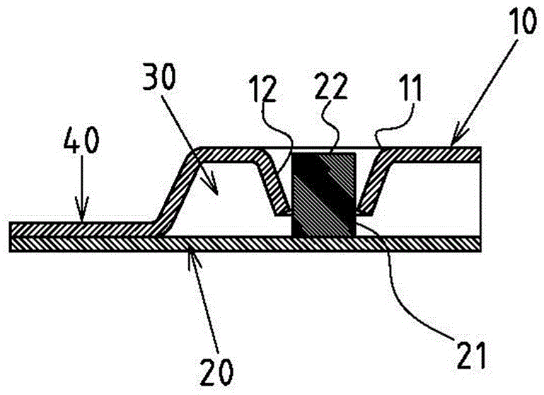
[0030] The temperature chamber A includes an upper cover plate 10 and a lower cover plate 20 stacked together, a hollow chamber 30 is formed inside the upper cover plate 10 and the lower cover plate 20, and the upper cover plate 10 and the lower cover plate The periphery of the plate 20 is combined and fixed by a ring-shaped pressing edge 40, so that the hollow chamber 30 is in a closed state; the sealing structure B includes the following components:

[0031] One side faces the opening type operation hole 11, and the plate surface opened on the upper cover plate 10 is in the form of communicating with the hollow chamber 30 at a position close to the annular pressing edge 40, so as to vacuumize and inject liquid i...


PUM


Abstract

A sealing structure for a vapor chamber comprises a face open type operation hole, an extension pipe part and a low-melting-point press-fit part. The face open type operation hole is formed in the position, close to an annular press-fit edge, of a plate face of an upper cover plate and is in a form that the face open type operation hole communicates with a hollow cavity, and accordingly the face open type operation hole can be used for vacuum pumping and liquid injection work of the hollow cavity. The extension pipe part is integrally formed in the face open type operation hole and is in a form that the extension pipe part extends in the hollow cavity in a protruding manner. The low-melting-point press-fit part is arranged on the inner face of a lower cover plate in a positioning state and located at the position, opposite to the position where the face open type operation hole is formed, in the upper cover plate, the upper end of the low-melting-point press-fit part upwards penetrates the extension pipe part in an extending manner, interval space is formed between the low-melting-point press-fit part and the extension pipe part, and a fusion pressed part is arranged at the upper end of the low-melting-point press-fit part and upwards protrudes and extends to the position of the upper end of the face open type operation hole. The melting point of the material of the low-melting-point press-fit part is lower than that of the material of the upper cover plate. The periphery of the upper cover plate and the periphery of the lower cover plate can be manufactured into the annular combined sealed state, the face open type operation hole of the sealing structure conforms to the good mechanism generatrix of related machining equipment, in addition, no welding flux needs to be used for welding and sealing, the manufacturing procedures are simpler, the problem of welding flux pollution is avoided, and environment friendliness is better achieved.

Description

technical field [0001] The invention relates to a temperature equalization plate, in particular to an innovative technology of the sealing structure of the temperature equalization plate. Background technique [0002] The structure of the existing vapor chamber is usually composed of an upper cover plate and a lower cover plate stacked together, and a combination and fixing process is applied to the periphery of the two; and wherein the periphery of the upper cover plate and the lower cover plate is in the After the joining and fixing steps are completed, a gap must be reserved for subsequent steps such as vacuuming and liquid injection inside the chamber, and then the gap is sealed by soldering. [0003] However, in the actual application experience, it is found that there are still some problems and disadvantages in the above-mentioned structure and molding method of the existing chamber, because the gap is usually formed around the upper cover plate when stamping out the ...

Claims


Application Information

Patent Timeline
Patent Type & Authority Applications(China)
IPC IPC(8): F28D15/02
CPCF28D15/0283
Inventor 何信威黄志仁吴学陞
Owner SUZHOU FORCECON ELECTRIC
Features
  • R&D
  • Intellectual Property
  • Life Sciences
  • Materials
  • Tech Scout
  • Unparalleled Data Quality
  • Higher Quality Content
  • 60% Fewer Hallucinations
Learn More