Multi-component fiber balance and measurement method thereof

A multi-component, balance technology, applied in measuring devices, fluid pressure measurement using optical methods, measuring fluid pressure, etc., can solve problems such as poor practicability of fiber optic balances

Inactive Publication Date: 2016-10-26
NORTHWESTERN POLYTECHNICAL UNIV
View PDF5 Cites 15 Cited by
  • Summary
  • Abstract
  • Description
  • Claims
  • Application Information

AI Technical Summary

Problems solved by technology

[0004] In order to overcome the shortcomings of poor practicability of the existing optical fiber balance, the present invention provides a multi-component optical fiber balance and its measurement method

Method used


Image

  • Multi-component fiber balance and measurement method thereof
  • Multi-component fiber balance and measurement method thereof
  • Multi-component fiber balance and measurement method thereof

Examples


Embodiment 1

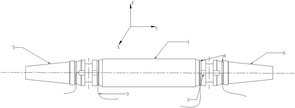
[0039] Example 1. The multi-component optical fiber balance of the present invention includes a balance main body 1, a notch 2, a fiber grating strain gauge 3, a wire groove 4, a support rod end 5 and a fixed end 6. The fixed end 6 is installed on the measuring platform by a fixing device. The balance main body 1 has a square groove in the circumferential direction at the positions close to the fixed end 6 and the supporting rod end 5. The square groove has four notches 2 and a total of eight at both ends. There are two notches 2, and the notches 2 are symmetrically arranged with the same size. The width of the notch is 10mm and the depth is 3mm. A fiber grating strain gage 3 is pasted in the center of each slot 2, a total of eight fiber grating strain gages 3, the lead wire of the fiber grating strain gage 3 is led out by the wire slot 4, and the length of the slot 2 is not less than the length of the grating area of ​​the fiber grating. Then the fiber is pre-stretched, the p...

Embodiment 2

[0040] Example 2. The specific steps of the measurement method of the multi-component fiber balance described in embodiment 1 are as follows:

[0041] Step 1. Fix the fixed end of the fiber optic balance on the measuring platform, and use the end of the support rod to load the load.

[0042] Step 2. Place one end of the fiber grating strain gauge freely, and fused the other end with the fiber jumper through the fiber fusion splicer. The fiber jumper transmits the optical signal and is input to the terminal fiber demodulator. The fiber grating demodulator has a built-in laser light source. The light source emits broad-spectrum light, which is transmitted to the grating area from the fiber jumper and fiber pigtail. The light of the wavelength that meets the conditions of the Bragg formula is reflected and transmitted through the fiber pigtail and fiber jumper. To the fiber grating demodulator, the fiber grating demodulator responds to the received optical signal as a wavelength valu...


PUM

PropertyMeasurementUnit
widthaaaaaaaaaa
depthaaaaaaaaaa
wavelengthaaaaaaaaaa

Abstract

The invention discloses a multi-component fiber balance and a measurement method thereof and aims to solve a problem of poor practicality of a fiber balance in the prior art. The multi-component fiber balance comprises a balance body, notches, fiber grating strain gauges, a wire duct, a pole end and a fixed end, wherein the fixed end is mounted on a measurement platform, portions of the balance body close to the fixed end and the pole end are respectively provided with a square groove circumferentially, the square groove has four notches, the notches are symmetrically arranged, and a center of each notch is bonded with one fiber grating strain gauge. During measurement, received light signals are converted by the fiber grating strain gauges into wavelength values which are displayed on a computer, lifting force, pitching moment, side force and yawing moment are applied, reflection wave center wavelength of the fiber grating strain gauges after load applying is measured, a relationship between the load and center wavelength offset can be calculated, and strong practicality is realized.

Description

Technical field [0001] The invention relates to an optical fiber balance, in particular to a multi-component optical fiber balance, and also relates to a measuring method of the multi-component optical fiber balance. Background technique [0002] The wind tunnel balance is a device that measures the aerodynamic forces and moments acting on the model in the wind tunnel, and is the most important measuring device in the wind tunnel test. [0003] The document "An optical fiber balance for wind tunnel test and measurement, the authorized announcement number is CN203658011U Chinese utility model patent" discloses an optical fiber balance for wind tunnel test and measurement, the optical fiber balance is symmetrically opened up and down at the root of the cantilever beam. Groove and paste an optical fiber strain gauge at the notch to measure the strain. Compared with the traditional strain balance, this method doubles the output sensitivity of the balance. This patent discloses only a ...

Claims


Application Information

Patent Timeline
Patent Type & Authority Applications(China)
IPC IPC(8): G01M9/06G01L11/02
CPCG01M9/062G01L11/025
Inventor 王勇解亚军高永卫焦予秦惠增宏邓磊白静
Owner NORTHWESTERN POLYTECHNICAL UNIV
Why Eureka
Try Eureka