
Interference direction method based on orientation deviation

A technology of azimuth deviation and azimuth, which is applied in the field of radar array signal processing, can solve the problem that multiple interference directions cannot be fully specified, and achieve the effect of convenient operation and improved accuracy

Active Publication Date: 2016-10-26
JINGZHOU NANHU MACHINERY CO LTD
View PDF4 Cites 0 Cited by
  • Summary
  • Abstract
  • Description
  • Claims
  • Application Information

AI Technical Summary

Problems solved by technology

At present, the method of selecting the maximum direction of the amplitude modulus of the interference signal is generally used to measure the interference angle. The method of selecting the maximum direction of the amplitude modulus of the interference signal is more accurate in distinguishing the interference between the interference signals with a large adjacent angle, but it is more accurate in distinguishing the phase between the interference signals. When the adjacent angle is small, the interference direction of multiple interferences cannot be fully specified

Method used


Image

  • Interference direction method based on orientation deviation
  • Interference direction method based on orientation deviation
  • Interference direction method based on orientation deviation

Examples


Embodiment Construction

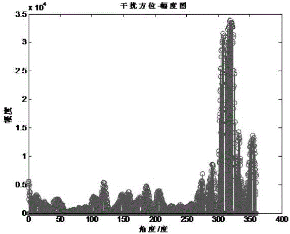
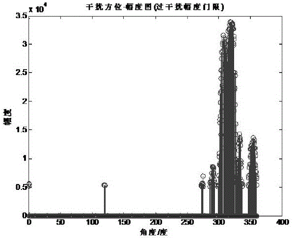
[0034] The implementation of the azimuth deviation-based interference pointing method will be described in further detail below with reference to the accompanying drawings: (see Figure 1 to Figure 7 )

[0035] A azimuth deviation-based interference pointing method, the hardware includes a TS201 DSP digital signal processing chip, hereinafter referred to as DSP, and the software includes Visual DSP++ software; the azimuth deviation-based interference pointing method adds azimuth to the interference signal amplitude value data read by the DSP Deviation value flag; including: 1) Interference amplitude threshold flag bit, used to confirm whether the interference amplitude of the sampling point can be regarded as interference; 2) Interference large area angle threshold flag bit, used to confirm the approximate sub-regional range of interference; 3) Interference sub-zone The zone angle threshold flag is used to judge whether the difference between the azimuth values ​​of the two ad...


PUM


Abstract

The invention relates to an interference direction method based on orientation deviation and belongs to the technical field of radar array signal processing. The method includes 9 steps with hardware including a TS201 type digital signal processing DSP chip and the software including a Visual DSP++software. The method increases orientation deviation value reading in for interference amplitude data that are read by the DSP chip, optimizes the usage of the orientation deviation value to obtain possible orientation of the interference, and determines the detailed orientation of the interference by assessing whether an interference amplitude is higher than an interference threshold. The method can clearly identify and differentiate two or a plurality of interferences having smaller separation angles, is easy to operate, and can at the same time indicate detailed direction on a terminal interface of a radar with a dotted line. The method overcomes the problems of current methods for measuring interference angles by selecting the maximum direction module value of the interference, such as failure of clearly identifying and differentiating a plurality of interferences having smaller separation angles, failure to indicate detailed direction on the terminal interface of the radar, and susceptibility to influence on the precision of interference direction angle of radar measuring.

Description

technical field [0001] The invention relates to an interference pointing method based on azimuth deviation, and belongs to the technical field of radar array signal processing. Background technique [0002] Azimuth bias is commonly used in radars with the ability to measure angles. When the radar uses the equal beam method to measure the angle, the left and right beams emitted by the radar have a certain deviation from the actual azimuth. The azimuth deviation value is the difference between the actual azimuth and the left and right beams, so the azimuth is increased in the direction of the left and right beams. Deviation value, you can get the actual bearing. At present, the method of selecting the maximum amplitude modulus value of the interference signal is generally used to measure the interference angle. In the case of interference with smaller adjacent angles, the interference directions of multiple interferences cannot be completely specified. SUMMARY OF THE INVEN...

Claims


Application Information

Patent Timeline
Patent Type & Authority Applications(China)
IPC IPC(8): G01S3/00
CPCG01S3/00
Inventor 刘志平宋万杰胡敏昝航刘帅
Owner JINGZHOU NANHU MACHINERY CO LTD
Learn More