Multi-rotor unmanned aerial vehicle self-adaptive landing method and system

A technology of multi-rotor drones and drones, applied in control/regulation systems, non-electric variable control, instruments, etc., can solve the problems of limited effects, crashes, bombings, and control without coordination and coordination of the landing state Algorithms and other issues

Active Publication Date: 2016-10-26
CENT SOUTH UNIV
View PDF7 Cites 43 Cited by
  • Summary
  • Abstract
  • Description
  • Claims
  • Application Information

AI Technical Summary

Problems solved by technology

[0004] 1. During the landing process, the operator needs to continuously adjust the position and attitude of the drone according to the actual situation on the ground until it lands smoothly. The whole process may take a long time to operate, which may easily cause eye fatigue or other discomfort reactions of the operator
[0005] 2. Manual operation increases the risk of landing. If you are not careful, you may collide with obstacles, and even cause crashes, explosions, etc.
However, there are three problems in this scheme: First, the UAV needs to continuously obtain flight status information and find the designated landing position point by image matching with the landing position mark (such as the "H" letter). Set up a landing flag (usually the letter "H"); secondly, the program does not provide a control algorithm or method for the coordination between the landing state and the normal flight state. The drone cannot land when it is forced to land and cannot find the scheduled landing point. Even if the drone detects the landing target point, it may crash at any time due to insufficient power during the fl

Method used


Image

  • Multi-rotor unmanned aerial vehicle self-adaptive landing method and system
  • Multi-rotor unmanned aerial vehicle self-adaptive landing method and system
  • Multi-rotor unmanned aerial vehicle self-adaptive landing method and system

Examples


Embodiment Construction

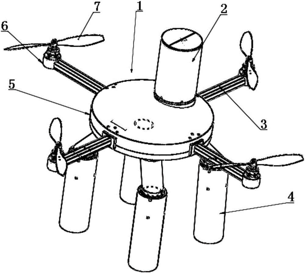
[0069] The present invention uses images taken by UAVs at different positions in the sky to determine several landing areas. After the UAV completes the task, it selects the nearest landing area and the best path to implement adaptive landing, and uses the designed retractable landing gear to reduce the impact on landing. The real-time out-of-control monitoring provided for UAVs can effectively and safely land in normal landings and emergency landings, protecting UAVs and their onboard electronic equipment.

[0070] In order to make the technical solutions and advantages of the present invention clearer and easier to understand, the technical solutions in the embodiments of the present invention will be specifically described below in conjunction with the accompanying drawings.

[0071] Specific embodiments of the present invention will be described in detail below in conjunction with the accompanying drawings.

[0072] see figure 1 , The multi-rotor UAV provided by the prese...


PUM


Abstract

The invention discloses a multi-rotor unmanned aerial vehicle self-adaptive landing method and system. When an unmanned aerial vehicle takes off, a ground control station (such as a tablet computer, a cell phone or other control equipment) chooses an approximately proper area for the unmanned aerial vehicle to land in. When the unmanned aerial vehicle receives the order to land, it starts the landing mode and waits the landing action to take place. The landing face of the landing area is then checked to see if it is suitable for the unmanned aerial vehicle to land or not. If it is suitable, the unmanned aerial vehicle begins to land and the landing mode ends; if it is not suitable, the pose of the unmanned aerial vehicle is changed for continued landing. According to the invention, it is possible to realize safe and reliable self-landing of an unmanned aerial vehicle even at a place where the landform is complex.

Description

technical field [0001] The invention relates to an adaptive landing method and system for a multi-rotor UAV. Background technique [0002] At present, the Multi-Rotor Unmanned Aerial Vehicle is the most rapidly developing and widely used aircraft among the types of UAVs. Using various electronic devices on board, it can realize image shooting and transmission, air early warning , natural disaster monitoring, power line inspection, pesticide spraying and other functions; it can also be equipped with active operating devices (such as mechanical arms) to form an operating flying robot system. Multi-rotor drones have the advantages of low cost, simple structure, easy manipulation, high flexibility, no runway for take-off and landing, hover control, and ultra-low-altitude flight. [0003] However, in order to achieve more functions, multi-rotor drones need to be equipped with a variety of equipment. Some airborne equipment has the function of collecting and sending important inf...

Claims


Application Information

Patent Timeline
IPC IPC(8): G05D1/06
CPCG05D1/0676
Inventor 谭冠政刘西亚陈佳庆王汐
Owner CENT SOUTH UNIV
Why Eureka
Try Eureka