An improved electrical connector

An electrical connector, an improved technology, applied in conductive connections, connections, circuits, etc., can solve problems such as insufficient strength, achieve low R&D costs, meet strength requirements, and increase the effect of cross-sectional area

Active Publication Date: 2018-05-15
SHANGHAI HOPPY ELECTRONICS ELECTRIC APPLIANCE +2
View PDF6 Cites 0 Cited by
  • Summary
  • Abstract
  • Description
  • Claims
  • Application Information

AI Technical Summary

Problems solved by technology

[0005] The purpose of the present invention is to provide an improved electrical connector, which solves the previous requirement that the thickness of the copper conductor of the terminal plate needs to be at least 1.5mm, and solves the problem of insufficient strength.

Method used


Image

  • An improved electrical connector
  • An improved electrical connector
  • An improved electrical connector

Examples


Embodiment Construction

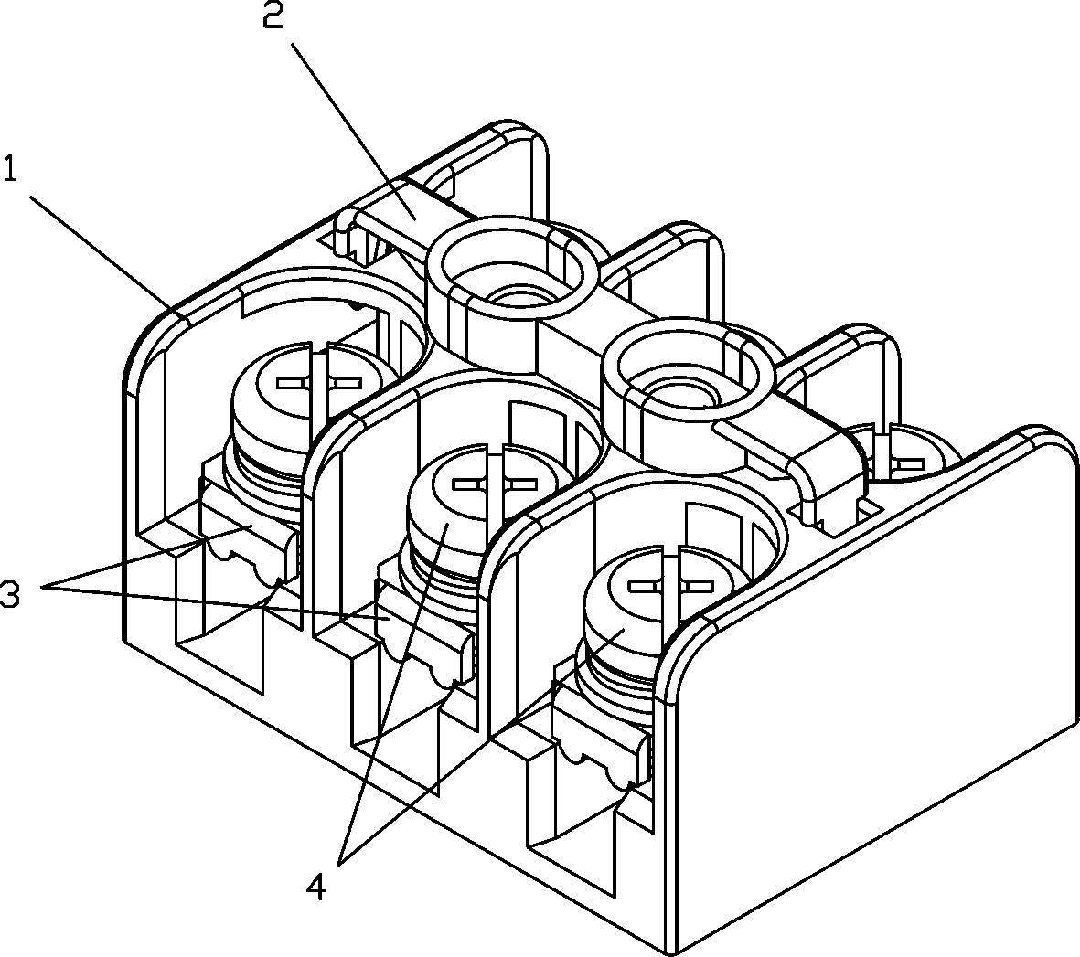
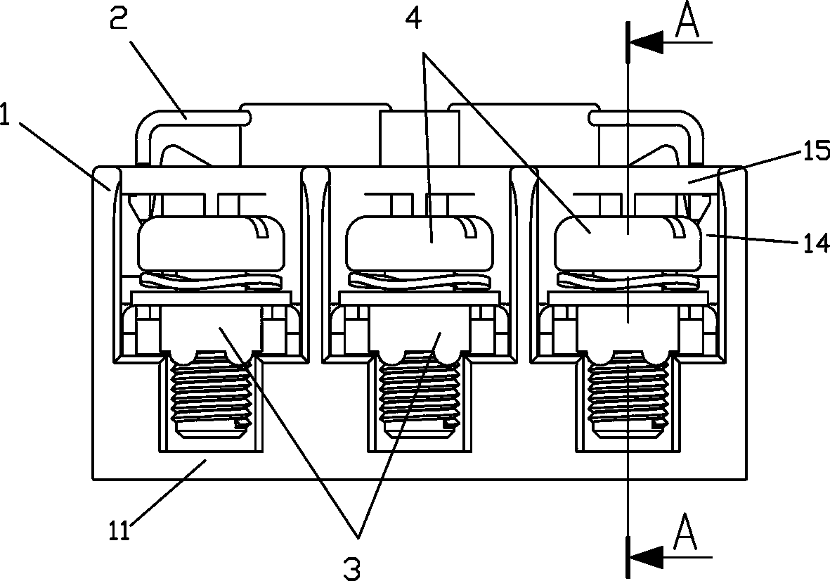
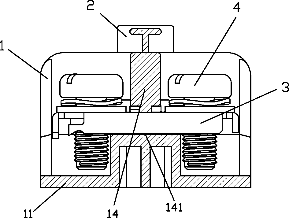
[0028] see Figure 1 to Figure 12 , an improved electrical connector of the present invention, which includes,

[0029] Insulating base 1, comprising,

[0030] Base plate 11, on which four longitudinal partitions 12, 12' are arranged side by side at intervals, and three parallel and independent compartments 13 are formed on the base plate 11 along the length direction (taking compartment 13 as an example, the same below), inside compartment 13 Inner support blocks 131, 132 on both sides;

[0031] A transverse partition 14 is plugged into the middle of the longitudinal partitions 12, 12', and divides the compartment 13 into several corresponding power supply side chambers and load side chambers along the width direction of the bottom plate; the transverse partition 14 is located at The middle part of each chamber is provided with a through hole 141 passing through the front and back;

[0032] A top plate 15 is connected to the top of each of the longitudinal partitions 12, 1...


PUM


Abstract

The present invention provides an improved electric connector. The connector comprises: an insulation pedestal consisting of a base plate which is provided with a plurality of vertical clapboards in parallel arranged at interval, wherein a plurality of parallel independent compartments on the base plate are arranged along the length direction, and support blocks are arranged at two sides in each compartment; a transverse clapboard inserted in the middle of the vertical clapboards, wherein a through hole is arranged at the middle of the transverse clapboard; a top board connected at the top end of each vertical clapboard, installation through hole through up and down is arranged at the middle portion of the top board, and necks or a connection through holes are arranged at two ends of the top board; an insulation lid which is in a plunger shape and includes a cylindrical tube body, connection portions at two sides and fixed portion formed by extending from the connection portions and bending downwards; a plurality of terminal boards, each having two ends provided with connection through holes, wherein the terminal boards are bended downwards to form support portions, and the terminal boards are inserted into a power supply cavity from a load cavity through the transverse clapboard and lapped at the upper ends of the support blocks at the two sides in each compartment; and a plurality of wiring locking screws respectively arranged in the connection through holes of the terminal boards.

Description

technical field [0001] The present invention relates to an improved electrical connector. Background technique [0002] Series combination wiring fixtures in electrical engineering. The number of terminal points in each row is different, and its model can be determined according to the needs of engineering technical parameters. In the wiring of power electronics, when the equipment in the screen is connected with the equipment outside the screen, it must pass through some special terminals. The combination of these terminals is called a terminal block. The function of the terminal block is to connect the lines of the equipment in the screen and the equipment outside the screen, and play the role of signal (current and voltage) transmission. With the terminal block, the wiring is beautiful and the maintenance is convenient. The connection between the long-distance lines is mainly reliable, and the construction and maintenance are convenient. [0003] Terminal block is an a...

Claims


Application Information

Patent Timeline
Patent Type & Authority Patents(China)
IPC IPC(8): H01R9/28
CPCH01R9/28
Inventor 毛兵兵
Owner SHANGHAI HOPPY ELECTRONICS ELECTRIC APPLIANCE
Why Eureka
Try Eureka