Nested high-reliability contact rotation system and its combined system and method
A nested and reliable technology, applied in the assembly/disassembly, connection, rotating current collector and other directions of contacts, can solve the problem of axial squatting, shaft jumping, and the external circuit of the rotating shaft and the internal circuit of the rotating shaft cannot be maintained for a long time without gaps Contact and other problems, to achieve the effect of stable rotation and reliable conduction
- Summary
- Abstract
- Description
- Claims
- Application Information
AI Technical Summary
Problems solved by technology
Method used
Image
Examples
no. 1 example
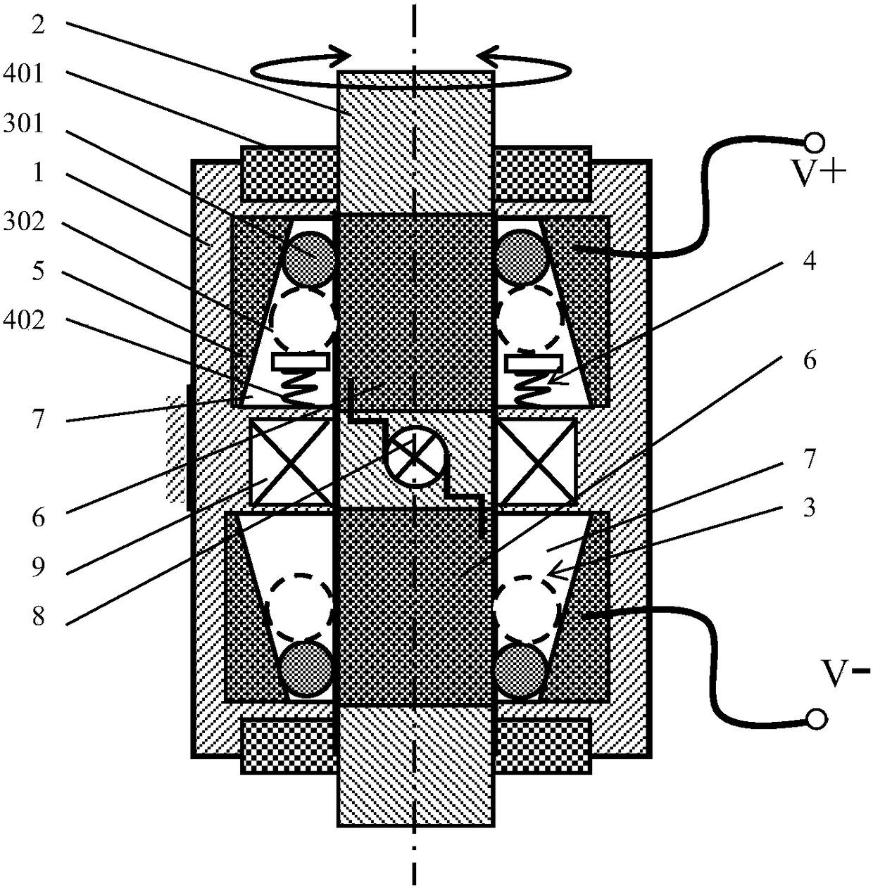
[0082] like figure 1 As shown, the moving contact body 3 includes a contact body ball 301, a contact body ring 302; the moving contact body applying mechanism 4 includes a force magnet 401 and a deformation force applicator 402; the force magnet 401 can be a permanent magnet or an electromagnet; The body 2 is a rotating shaft; the gap between the first contacted body 5 and the second contacted body 6 forms a channel 7 along the axial direction of the rotating body 2 from wide to narrow; the moving contact body 3 moves in the channel 7;
[0083] Wherein, the quantity of contact body sphere 301 is one or the quantity of contact body sphere 301 is multiple, there are more than 2 contact body spheres 301 with equal ball diameters and / or there are unequal ball diameters in multiple contact body balls 301 2 or more contact balls 301 . Passage 7 is annular and surrounds the axis of rotating body 7 in the circumferential direction; Multiple passages 7 can be distributed in the circum...
no. 2 example
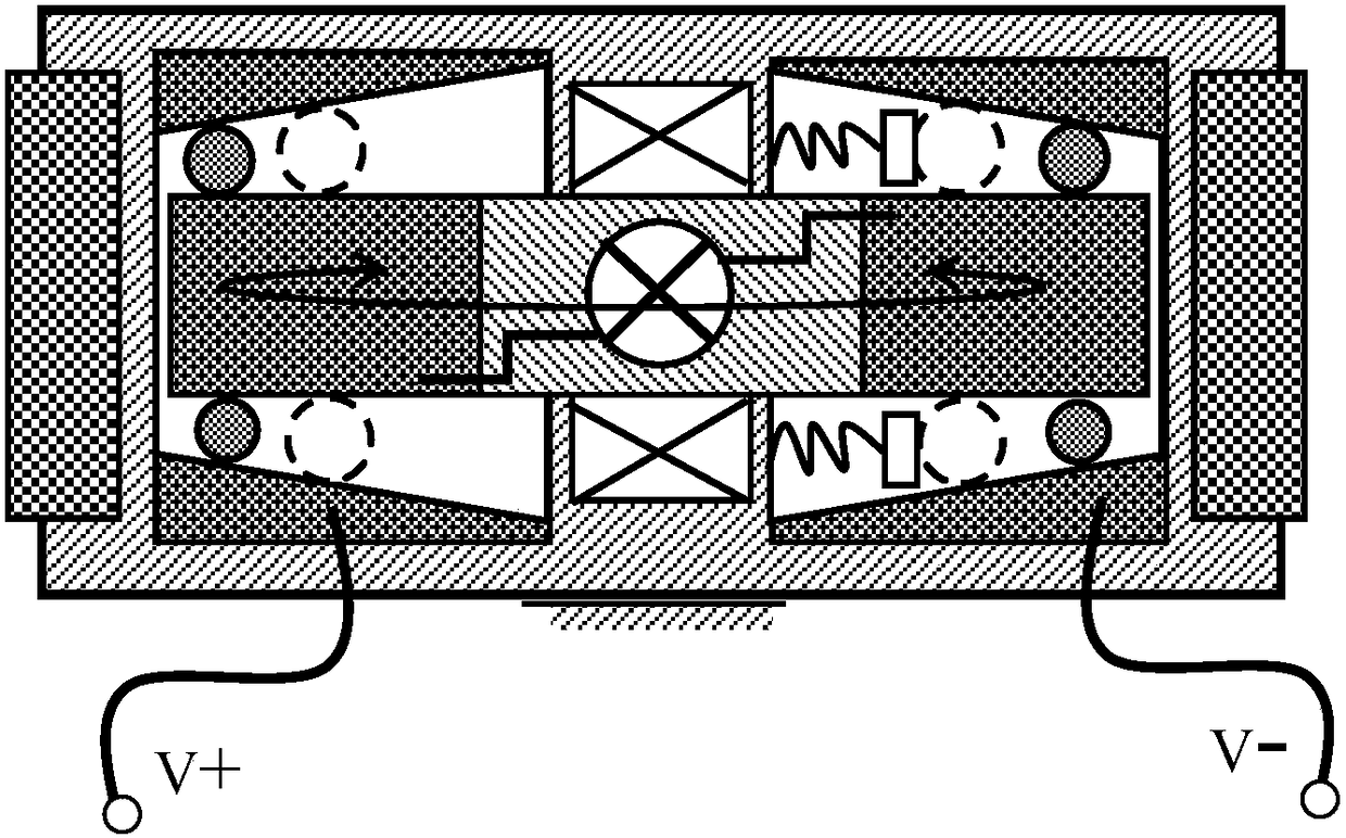
[0087] The second embodiment can be understood as a modification of the first embodiment, the difference is that in the second embodiment, the rotating body 2 is a turntable, and the rotation direction of the turntable is as follows: figure 2 in the direction of the arrow. figure 1 A mounting magnet 9 is shown, represented by two crossed boxes; figure 2 Two mounting magnets 9 are shown, represented by two crossed boxes located on the upper and lower sides of the turntable respectively.
no. 3 example
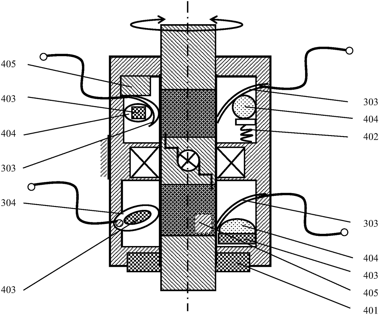
[0089] like image 3 as shown, image 3 Four different modes of the moving contact body 3 and the moving contact body force application mechanism 4 are shown.
[0090] like image 3 The implementation of the moving contact body 3 and the moving contact body force mechanism 4 shown in the upper left corner, the moving contact body 3 includes an elastic contact body 303, and the elastic contact body 303 has a free end or a free end in contact with the second contacted body 6. End; the moving contact body force applying mechanism 4 includes a permanent magnet following moving body 403 and an elastic following moving body 404; the permanent magnet following moving body 403 is fastened to the elastic following moving body 404; the moving contact body applying force mechanism 4 also includes: iron A magnet 405; wherein, under the attraction of the ferromagnet 405, the permanent magnet follower 403 is pressed tightly against one side of the elastic contact body 303 through the elas...
PUM
 Abstract
Description
Claims
Application Information
 - R&D
- Intellectual Property
- Life Sciences
- Materials
- Tech Scout
- Unparalleled Data Quality
- Higher Quality Content
- 60% Fewer Hallucinations
Browse by: Latest US Patents, China's latest patents, Technical Efficacy Thesaurus, Application Domain, Technology Topic, Popular Technical Reports.
© 2025 PatSnap. All rights reserved.Legal|Privacy policy|Modern Slavery Act Transparency Statement|Sitemap|About US| Contact US: help@patsnap.com


