
Power supply system remote monitoring system

A remote monitoring system and power supply system technology, applied in the direction of power network operating system integration, information technology support system, electrical components, etc., can solve problems such as increased line and transformer load, local fault expansion, and unsatisfactory grid voltage level

Active Publication Date: 2016-10-26
国网山东省电力公司泗水县供电公司 +1
View PDF6 Cites 51 Cited by
  • Summary
  • Abstract
  • Description
  • Claims
  • Application Information

AI Technical Summary

Problems solved by technology

[0003] In this way, driven by the development of the national economy, there has been a phenomenon of power cuts; the composition of the load has changed, and the residential and commercial power consumption has increased significantly, which has increased the load on some lines and transformers, and even caused partial power outages due to overload; Due to the expansion of local faults caused by the defects of the power system itself, large-scale and long-term power outages occur; because the reactive power supply configuration and adjustment methods do not adapt to the load development, the grid voltage level cannot meet the power quality requirements, resulting in damage to electrical equipment and even occurrence of power failures. Power outage accidents caused by voltage collapse; there are problems with excessive network loss during the operation of the distribution network, etc.

Method used


Image

  • Power supply system remote monitoring system
  • Power supply system remote monitoring system
  • Power supply system remote monitoring system

Examples


Embodiment Construction

[0098] In order to make the purpose, features and advantages of the present invention more obvious and understandable, the technical solutions protected by the present invention will be clearly and completely described below using specific embodiments and accompanying drawings. Obviously, the implementation described below Examples are only some embodiments of the present invention, but not all embodiments. Based on the embodiments in this patent, all other embodiments obtained by persons of ordinary skill in the art without creative efforts fall within the protection scope of this patent.

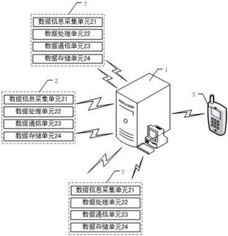
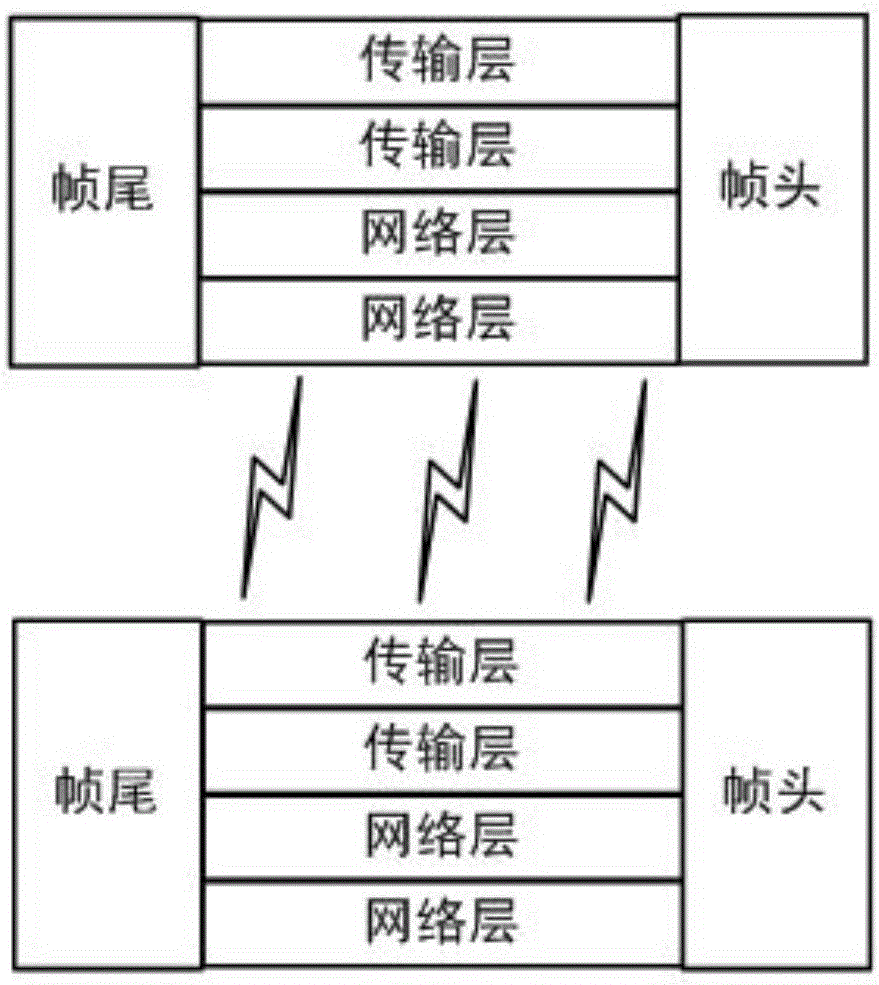
[0099] This embodiment provides a remote monitoring system for a power supply system, such as figure 1 with figure 2 As shown, it includes: a data information control subsystem 2 and a cloud server 1 respectively arranged at each monitoring point of the power distribution network;

[0100] The data information control subsystem 2 includes: a data information acquisition unit 21, a data ...


PUM


Abstract

The invention provides a power supply system remote monitoring system. A transformer equipment data acquisition module acquires the analog quantity of field transformer equipment and the current, voltage, active power, reactive power, coil temperature and oil temperature at each side of the transformer. A power supply circuit data acquisition module acquires the current, active power and reactive power of a power supply line, the voltage and frequency of a bus, and the three-phase voltage, three-phase current, zero-sequence voltage and zero-sequence current of the power supply line. A circuit breaker data acquisition module, an isolating switch data acquisition module and a grounding switch data acquisition module are respectively used for acquiring the switching quantity of the field equipment. Through a monitoring platform, systematic data storage is performed, monitoring clients can be connected to share data information, and grid maintenance personnel can exchange knowledge and accumulate data. Typical cases are formed based on stored maintenance process logs, maintenance process cases and related standard or specification files. Related standards, specification documents and operation procedures are provided. Knowledge and experience sharing and management are realized.

Description

technical field [0001] The invention relates to the field of power supply, in particular to a remote monitoring system for a power supply system. Background technique [0002] The distribution network is at the end of the power system, and has the distinctive characteristics of wide geographical distribution, large-scale power grid, various types of equipment, various network connections, and variable operation modes. With the urbanization construction and the growth of electricity demand, the distribution network has been continuously transformed and expanded, and its scale has also been continuously expanded. The scale of most county-level and above distribution networks in the State Grid Corporation system has reached hundreds of feeders. Above, the number of medium voltage feeders in some medium and large cities has reached or exceeded one thousand. [0003] In this way, driven by the development of the national economy, there has been a phenomenon of power cuts; the co...

Claims


Application Information

Patent Timeline
IPC IPC(8): H02J13/00
CPCH02J13/0006Y02B70/30Y04S20/242
Inventor 张新强张长斌冯烨张辉刘腾颜丙胜杨春燕王守伟张宇琦张珂孙兴波
Owner 国网山东省电力公司泗水县供电公司
Learn More