
a detector

A detector and coupling technology, applied in the field of detectors, can solve the problems of reducing the signal-to-noise ratio, difficult digital program processing, and increasing digital signal processing, so as to avoid interference, the signal-to-noise ratio is not easily impaired, and the operating frequency is reduced. Effect

Active Publication Date: 2018-07-17
RICHWAVE TECH CORP
View PDF6 Cites 0 Cited by
  • Summary
  • Abstract
  • Description
  • Claims
  • Application Information

AI Technical Summary

Problems solved by technology

[0002] Generally speaking, a detector that uses the Doppler effect to detect the movement of the object under test needs to provide a high-frequency input signal through a high-frequency oscillation source to update the movement of the object under test. Most of the digital processing is done by analog processing, so semiconductor components are extremely susceptible to flicker noise, which seriously degrades the signal noise ratio and increases the subsequent digital signal processing (DSP) ) difficulty

Method used


Image

  • a detector
  • a detector
  • a detector

Examples


Embodiment Construction

[0067] Specific embodiments of the present invention will be described in detail below in conjunction with the accompanying drawings. However, the present invention should be understood as not limited to such embodiments described below, and the technical idea of ​​the present invention can be implemented in combination with other known technologies or other technologies having the same functions as those known technologies.

[0068] In the description of the following specific embodiments, in order to clearly demonstrate the structure and working mode of the present invention, many directional words will be used to describe, but "front", "rear", "left", "right", "outer Words such as ", "inwardly", "outwardly", "inwardly", "axially" and "radially" are to be understood as convenient terms and should not be understood as limiting terms.

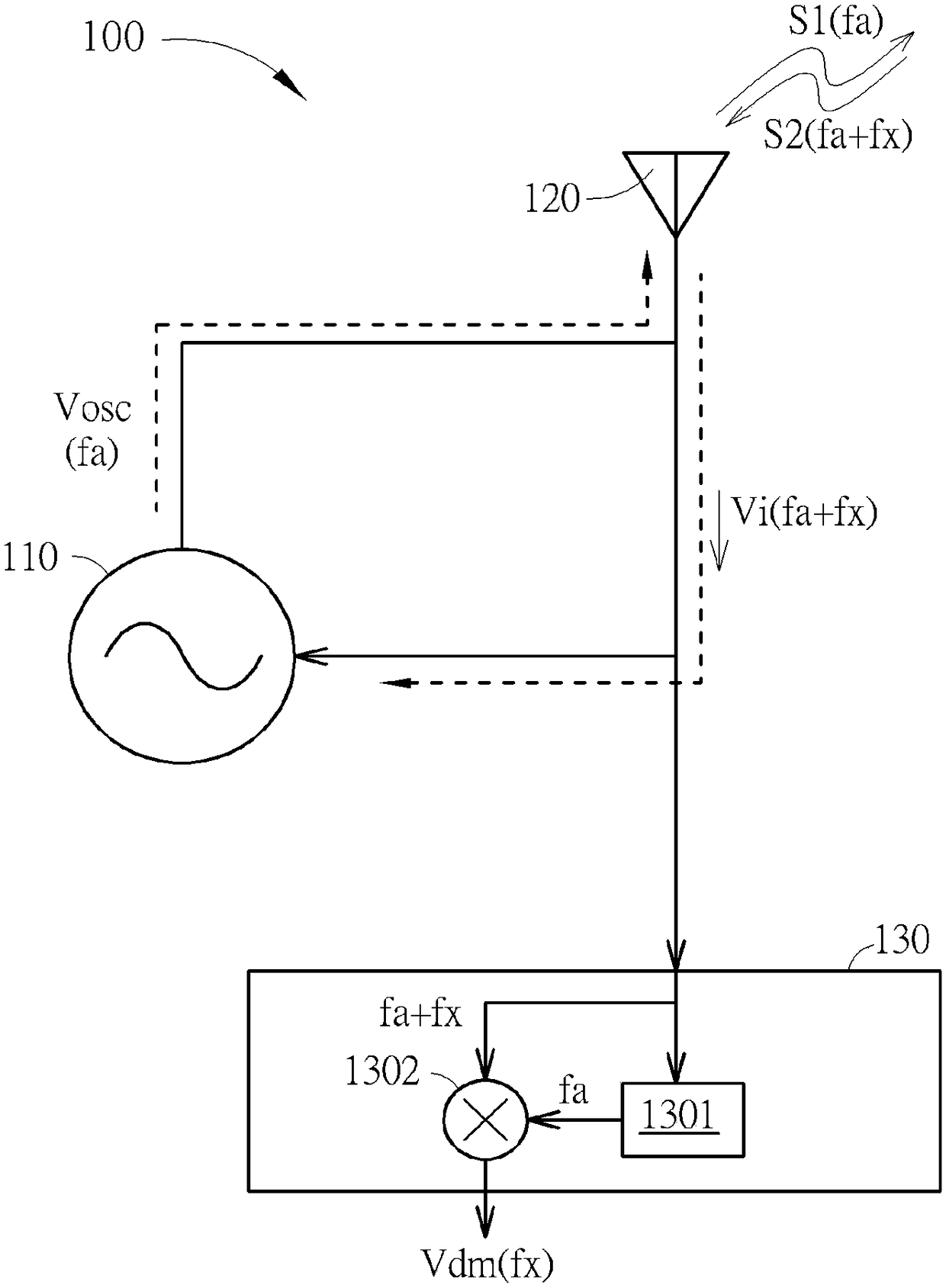
[0069] figure 1is a schematic diagram of a detector provided by an embodiment of the present invention. The detector 100 includes an oscilla...


PUM


Abstract

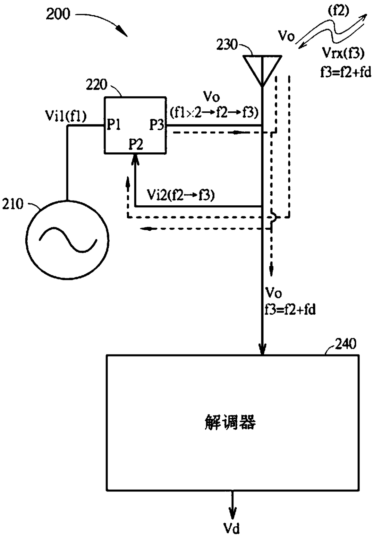
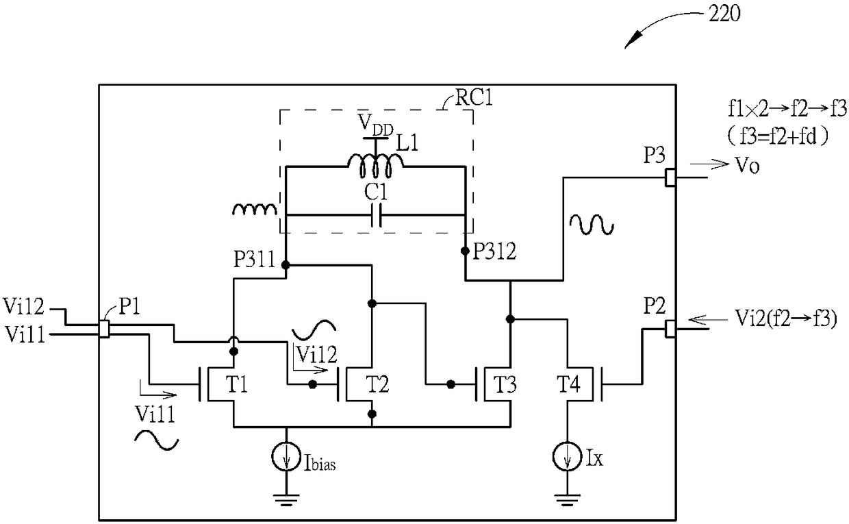
The invention discloses a detector, which includes an oscillation source, a frequency multiplication unit, a transceiver unit and a demodulation unit. The oscillating source generates a first injection signal with a first frequency. The frequency multiplying unit receives the first injection signal, outputs an output signal and receives a second injection signal with a second frequency. The frequency multiplying unit locks the frequency of the output signal to a multiple of the first frequency by injection locking, and pulls the frequency of the output signal to the second frequency by injection pulling. The transceiver unit transmits the output signal and receives a received signal with a third frequency, the received signal is used to update the second injection signal. The demodulation unit performs a demodulation operation according to the output signal to generate a displacement signal.

Description

technical field [0001] The present invention relates to a detector, in particular to a detector comprising a frequency multiplication unit to inject and pull to generate an output signal. Background technique [0002] Generally speaking, a detector that uses the Doppler effect to detect the movement of the object under test needs to provide a high-frequency input signal through a high-frequency oscillation source to update the movement of the object under test. Most of the digital processing is done by analog processing, so semiconductor components are extremely susceptible to flicker noise, which seriously degrades the signal noise ratio and increases the subsequent digital signal processing (DSP) ) difficulty. In addition, since the oscillation source works at high frequency (for example, about 10G Hz), it is difficult to lower the frequency, so the power consumption of the oscillation source is difficult to reduce. Therefore, there is a real need in the art for a soluti...

Claims


Application Information

Patent Timeline
Patent Type & Authority Patents(China)
IPC IPC(8): H04B17/30
CPCH04B17/30G01S7/35H03B19/14H03B2200/0074H03B2200/0082H03B2200/0088G01S7/034G01S13/536H04B1/10H04L1/0053H03L7/099H03L7/0802
Inventor 陈则朋
Owner RICHWAVE TECH CORP
Learn More