Limiting displacement device of mold slider

A technology of displacement device and die slider, applied in the field of die auxiliary device, can solve the problems of high maintenance cost, complex structure and high price, and achieve the effects of low cost, simple and effective limit structure and convenient maintenance.

Pending Publication Date: 2016-11-02
叶青
View PDF0 Cites 0 Cited by
  • Summary
  • Abstract
  • Description
  • Claims
  • Application Information

AI Technical Summary

Problems solved by technology

[0003] Now, in the mold design, it is often necessary to limit the moving stroke of the slider on the mold, so that the moving block can move within the moving distance, so as to prevent the moving distance from being too large, resulting in the produced product size not meeting the requirements. At present, there are few such limit devices on the market. Some imported limit devices are expensive, have complex structures, high maintenance costs, and are easily damaged.

Method used


Image

  • Limiting displacement device of mold slider

Examples


Embodiment Construction

[0010] In order to deepen the understanding of the present invention, the present invention will be further described below in conjunction with the embodiments and accompanying drawings. The embodiments are only used to explain the present invention and do not constitute a limitation to the protection scope of the present invention.

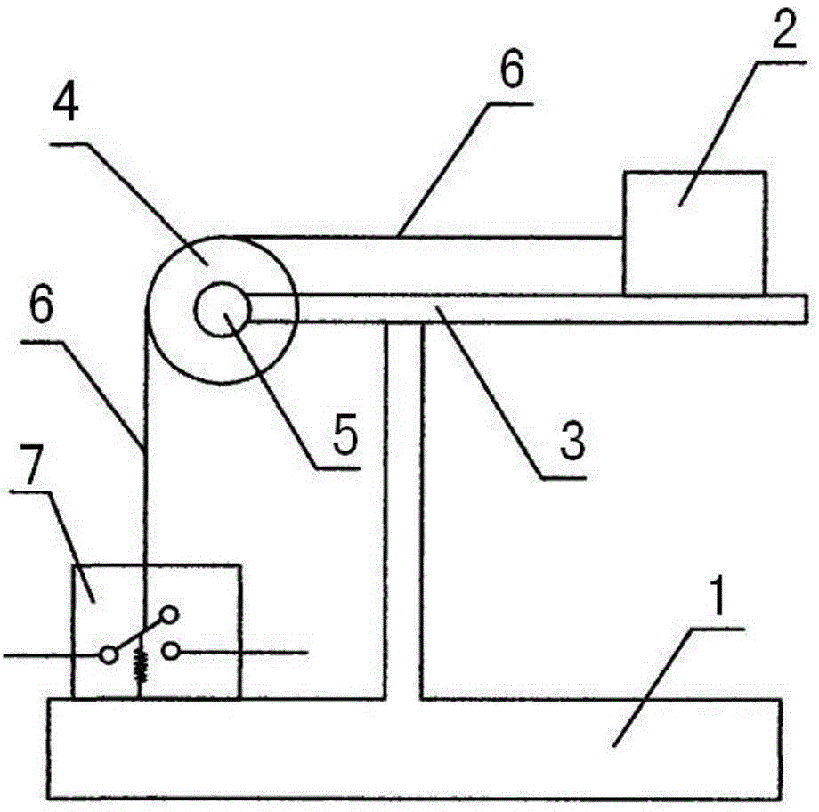
[0011] figure 1 It shows an embodiment of a displacement limiting device of a mold slider in the present invention, including a base 1 and a slider 2, a slide table 3 is arranged on the base 1, and slide rails are provided on the slide table 3, The slide block 2 is slid on the slide table 3 along the slide rail, and a rotating pulley 4 is installed on one side of the slide table 3. The pulley 4 rotates around the rotating shaft 5 fixed on the slide table. The base 1 A return switch 6 is also fixed on the top, and a drawing wire 7 is also provided. One end of the drawing wire 7 is fixed on the slider 2, and the other end is connected to the return...


PUM


Abstract

The invention discloses a displacement limiting device of a mold slide block, comprising a base and a slide block, a slide table is arranged on the base, a slide rail is arranged on the slide table, and the slide block is arranged on a slide rail along the slide rail. On the platform, a rotating pulley is installed on one side of the sliding platform, and the pulley rotates around the rotating shaft fixed on the sliding platform. A return switch is also fixed on the base, and a drawing is also provided. One end of the drawing It is fixed on the slide block, and the other end is connected to the return switch, and the return switch is connected with the driving device for controlling the sliding of the slide block. Such a limiting structure is simple and effective, can accurately limit the stroke of the slider, and effectively improves the precision of mold production, and the device has low cost and is easy to maintain, and is suitable for various small mold production.

Description

technical field [0001] The invention relates to a mold auxiliary device, in particular to a displacement limiting device of a mold slider. [0002] Background technique [0003] Now, in the mold design, it is often necessary to limit the moving stroke of the slider on the mold, so that the moving block can move within the moving distance, so as to prevent the moving distance from being too large, resulting in the produced product size not meeting the requirements. At present, there are few such limit devices on the market, and some imported limit devices are expensive, have complex structures, high maintenance costs, and are easily damaged. Contents of the invention [0004] In order to overcome the above-mentioned defects, the present invention provides a displacement limiting device of a mold slider with simple structure, low cost and convenient maintenance. [0005] The technical solution adopted by the present invention in order to solve the technical problem is: a...

Claims


Application Information

Patent Timeline
Patent Type & Authority Applications(China)
IPC IPC(8): B29C33/00
Inventor 叶青
Owner 叶青
Why Eureka
Try Eureka